
I deployed a test system and dumped its network traffic using the Capture Filtering function in Wireshark with certain conditions (see below).

Let’s sequentially open each dumped packet and examine the encapsulated data for network design information. Then the obtained information will be displayed graphically using the diagrams.net resource.
Channel and network addresses of first devices
The first four packets clearly indicate that some device receives an IP address and other network parameters via DHCP. Let’s open the first packet.

You can immediately see the MAC address of the client device. You don’t know the network address of this device (since it hasn’t received it yet); however, you see that destination addresses are broadcast ones.
You can also see IP address 192. in the 50 header section. This indicates that the client is requesting this particular IP address (perhaps, it had received it in the past?). But for now, it would be premature to display it on the diagram: let’s wait for the final response from the DHCP server.
And the last thing in this packet that requires your attention is the 12 option. The device name is displayed there. Now let’s transfer the collected data to the diagram.

The next packet is DHCP Offer: in response to the client’s message, the server offers possible network parameters.

As you can see, the IP address of the DHCP server that has responded to the client’s request is 192.; while its MAC address is 00:. The server offered to the client IP address 192. (by the way, the one requested by the client, see the Your IP address field) and the network mask 255.. Great, let’s add the new data to the diagram.

For clarity, I will highlight new elements in red.
Microsoft Windows and Cisco IOS, or what has TTL to do with it?
The DHCP message doesn’t contain any new information, except for the option 55 where the client requests additional parameters from the DHCP server: netmask, gateway address, DNS server, and domain name.

Also note the Time to Live field in the IPv4 header of this message.

The TTL value determines the lifetime of a packet. This value is decremented by one every time a packet passes through a routing device on the way to its destination.
The point is that different operating systems have their own default TTL values.
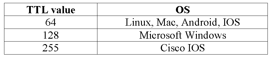
Since the TTL value in the client’s DHCP message is 128, you can assume that this is a Windows device.

The last message indicating that the interaction between the client and the DHCP server has been successfully completed is DHCP .

In this message, the DHCP server assigns to the client:
- IP address
192.(Your IP address field);168. 30. 2 - network mask
255.(option 1);255. 255. 128 - gateway
192.(option 3); and168. 30. 1 - DNS
8.(option 6).8. 8. 8
In addition, time intervals are set for address lease, renewal, and address requests from other local DHCP servers if the previous server becomes unavailable (options 51, 58, and 59, respectively).
Finally, let’s take a look at the TTL value of the IP packet from the DHCP server.

A TTL value of 255 indicates Cisco IOS. You can even identify the device manufacturer based on its MAC address using publicly available online services.

In other words, a Cisco router acts as a DHCP server on the network. After examining just four intercepted packets, you can construct the following network diagram.

Opening ARP и TCP
Time to open the fifth ARP packet (or, to be specific, frame)

Host 192. uses broadcasting to find out the MAC address of host 192.. The 1 value in the Opcode field indicates that this is a request (2 indicates a response). If you look at the screenshot showing the full dump at the beginning of the article, you won’t see a response to the ARP request there. Therefore, the existence of host 192. remains in question.

Packets 6 and 7 are basically the same.

Host 192. doesn’t receive a response and attempts to reestablish a TCP session with the web server (as indicated by the destination port 443) by sending SYN requests. Let’s add a web server and a Windows (since TTL = 128) host to the diagram.

How informative is CDP?
The CDP protocol is used to detect adjacent network devices running Cisco IOS and contains plenty of useful information. Let’s take a closer look at its most interesting fields.

First of all, note the carrier Ethernet frame: its destination address is multicast. And if you look at the source address (00:), it becomes clear that this is the MAC address of the router already present in your diagram.
Next, note the Device ID field whose value is gateway. This is the device name assigned using the hostname command in Cisco IOS.
The subsequent fields (Software and Platform) indicate the firmware version and device model, respectively. It turns out that you are dealing with a Cisco 2821 router running C2800NM-ADVIPSERVICESK9-M, Version 12.4(3f), RELEASE SOFTWARE (fc3). Let’s display this information in the diagram and proceed further.

The Port ID field contains the name and number of the device port through which this CDP packet was sent. In this particular case, this is port GigabitEthernet0/. Time to put the puzzle together: you just found out that the CDP packet was sent through port G0/, and the sender’s MAC address in the Ethernet header is 00:. This makes it possible to conclude that MAC address 00: belongs to port G0/.

But there is more! Look at the Addresses field whose value is 192.. This indicates that the IP address of the interface from where the CDP packet was sent (G0/) is 192.. At first glance, it’s no big deal, but let’s go back and look at the fourth DHCP ACK packet: in that message, the DHCP server who has responded to the client has an IP address of 192. and – importantly! – a MAC address of 00:! But you have already found out that port G0/ has IP address 192. and MAC address 00:. It turns out that there are two IP addresses on port G0/: 192. and 192..
How can this happen? Apparently, the network under investigation uses the ‘router on a stick’ method for routing between VLANs. In this routing scheme, the router is connected to the switch with a single wire; logical subinterfaces are created on the physical interface of the router; and IP addresses are assigned to them from different subnets. Note that their MAC addresses are identical since they are parts of the same physical port (in this particular case, port G0/). Let’s display this in the diagram as simply as possible.

Since you have found out that this network consists of at least two computers that are connected to the same physical interface of the router, then, most probably, there is some kind of switch between them.

The last field to be examined in the CDP packet is IP Prefixes. In this particular case, it has three values: 192., 192., and 66.. Each value represents one of the IP network segments directly connected to the router. You are already aware of the 192. and 192. networks, but the 66. segment appears for the first time. Nevertheless, one of the router’s interfaces is part of this network segment.
Routing Information Protocol

Routing Information Protocol (RIP) is an obsolete internal dynamic routing protocol. Its distinctive features are as follows: UDP port 520, multicast IP address 224., and multicast MAC address.
The sender’s MAC address is definitely familiar to you. Therefore, this message was sent to the internal user network that, most likely, doesn’t have other routers. Accordingly, port G0/ isn’t configured as passive on this router.
Perhaps, you expected the TTL value to be 1, but in reality it’s 2. This ensures that the RIP protocol can work in NBMA networks. In fact, there is nothing of interest there. Let’s examine the RIP header.
The Command field indicates the message type: for a request, its value is set to 1; while for a response or reply, it’s set to 2. But this doesn’t mean that someone has requested routing information from this router since RIP broadcasts it out every few seconds.
The Version field indicates (surprise!) the RIP protocol version. The only difference between the first and second versions is that the second one supports classless addressing. In simple words, in addition to network-related data, RIPv2 transmits information about masks of these networks, which makes it at least slightly useful nowadays.
Fields that display information about networks that can be accessed via your router are of utmost interest. IP is the destination network address. In this particular case, there are two of them: 192. and 66.. Metrics for both routes are equal to 1. In other words, to access these networks, another router has to make one hop to the destination. Hopefully, the meaning of the Netmask field doesn’t require explanation.
Router is used to separate internal routes (routes for networks within the RIP routing domain) from external routes that could be imported from EGP or another IGP.
The Next Hop value is set to 0. if the network is directly connected to the router (i.e. the sending router says that it acts as a hop on the way to the destination network).
One might ask: why network 192. isn’t in the announcement? But if you look at the IP header, you can see that the source IP address is 192., which is part of the 192. network. Therefore, there’s no need to announce information about the same network.
Summing up: analysis of the RIP packet confirms that network 66. is directly connected to the Cisco Router.

Three-way handshake and HTTP request

Here you see the TCP protocol again, but the IP and MAC addresses seem to be unfamiliar. Let’s examine them. Some 192. whose MAC address is f0: attempts to communicate with some 5. by sending a SYN request to the default gateway 00: (Cisco Router).
In addition, the well-known destination port 80 can be seen in the TCP header. In other words, host 192. attempts to establish a TCP session with the HTTP server. Also, if you look at TTL (whose value is 64), you can assume that the session is initiated by a Unix system. Let’s add this information to the diagram.

Based on packets 11 and 12, the TCP session establishment process continues, and the server sends a pair of SYN/ACK flags to the client. Now look at the server’s TTL: its value is 49, which presumably indicates a Unix OS on the web server side. As you remember, a packet sent by a server passes through a certain number of routing devices, and every time its TTL value decreases by one.

And only when the TCP session is established, the client generates an HTTP request. Let’s examine it.

There is nothing of interest there, except that the client requests the http:// web page.
Voila! You have examined the last intercepted packet and constructed the diagram below.

It displays all useful information extracted from the damp. Now let’s put some finishing touches to make the diagram more understandable.

Conclusions
As you can see, analysis of just 13 network packets gives you plenty of valuable information about the network under investigation. The above-described approach to visualization can be useful, for instance, when you are searching for incidents on the network or perform troubleshooting. The ability to ‘read’ network traffic will definitely boost your technical and networking skills and give a better understanding of interactions between network devices and protocols.
Good luck!