One day, GS Labs research and development center launched a project to identify possible bugs and vulnerabilities in its systems. However, the tested device chosen to run the application was pretty tricky: no way to install the root and no Ethernet connection. The only available communication methods were Wi-Fi and a remote control with a few buttons – so, who knows what’s going to be transferred via Wi-Fi? Hackers do not like uncertainty. Hackers like certainty. I had a couple of ESP32-based debug boards at home (the ESP32-PICO-KIT), and decided to build a Wi-Fi sniffer with the potential to be upgraded to a Bluetooth sniffer.


[panel]
Glossary
- AP (Access Point) – a networking hardware device that allows other Wi-Fi devices to connect to a wired network.
- BSSID (Basic Service Set Identifier) – normally, this refers to the media access control (MAC) address of the access point.
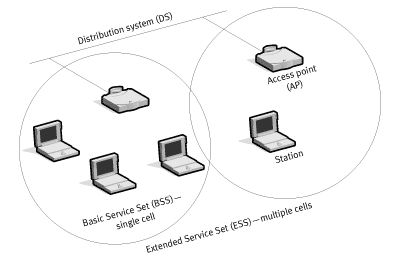
- BSS (Basic Service Set) – a group of devices successfully synchronized for communication using 802.11 standard.
- DA (Destination Address) – a MAC address of the final destination.
- DS (Distribution System) – a system connecting the basic service set (BSS) and LAN.
- ESS (Extended Service Set) – several basic service sets constituting together the DS.
- MPDU (MAC Protocol Data Unit) – an 802.11 data frame.
- MSDU (MAC Service Data Unit) – a payload containing an IP packet + LLC data.
- PLCP (Physical Layer Convergence Procedure) – a sublayer (the Physical layer (PHY) is divided into two sublayers in the 802.11 standard) responsible for the transmission of frames received from the MAC layer.
- PSDU (PLCP Service Data Unit) – an equivalent to the MPDU. The MAC layer refers to the frame as an MPDU (looking ‘down’ at it in the OSI model), while the Physical layer refers to this same frame as the PSDU (looking ‘up’ at it in the OSI model).
- SA (Source Address) – the MAC address of the original source.
- STA (Station) – any device supporting the 802.11 standard, including your smartphone, laptop, or Raspberry Pi 3.
[/panel]
Hardware
Microcontrollers belonging to the STM32Fxxx family are pretty popular today. Here, the “xxx” represents letters and digits indicating the device class: from Ultra-Low Power to High Performance. However, a couple of years ago, a wonderful chip named ESP32 (a successor to famed ESP8266 microcontroller) has hit the market.
Initially, the technical documentation for this chip was scarce. Today, the situation is different. An excellent user guide is available online; it provides step-by-step instructions on all aspects from SDK and toolchain installation to descriptions of peripherals. Plenty of practical examples can be found on GitHub.com. In addition, there is a very good tutorial explaining in detail how to deal with various peripherals.
Espressif Systems provides instructions on toolchain installation for all popular platforms.

The documentation is presented in two threads:
- the “latest” thread includes all modern and advanced SDK features whose testing is not completed yet; and
- the “stable” thread (at the time of the writing, it was version 3.1.2) that does not include some innovations but is recommended for production purposes.

There is also a forum where you can discuss anything about ESP32. In most cases, the technical support team of Espressif Systems provides prompt answers to users’ questions.
I will briefly repeat the main specifications of the ESP32 chip.
-
32-bit MCU Xtensa® single-/dual-core 32-bit LX6 microprocessor(s) supporting a broad range of frequencies;
-
520 KB SRAM;
- a ‘standard’ set of peripheral interfaces including UART/SPI/I2C, SDcard, Ethernet MAC (RMII), and CAN2.0;
- Wi-Fi (802.11b/g/n); and
- Bluetooth (Bluetooth v4.2 BR/EDR and BLE specifications).
The developers made a generous gift to assembler fans by installing an ULP (Ultra Low Power) co-processor that can be coded in assembler and consumes 150 µA in the Deep Sleep mode. Overall, there are tons of helpful information in the datasheet available on the Espressif Systems’ website.
You can find different ESP32 versions in stores; for example, this chip, which is only 2 cm in size while integrating an antenna switch
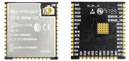
cost some $4-5.
Wi-Fi theory (yes, we will need it)
I will try to summarize three thousand pages in a few sentences. An ambitious mission, isn’t it?
Most probably, you are aware that the term “Wi-Fi” is applied to a broad range of 802.11 standards. Here are some examples:
- 900 MHz – 802.11ah;
- 2.4 GHz – 802.11b, 802.11g, 802.11n, 802.11ax;
- 3.6 GHz – 802.11y;
- 4.9 GHz – 802.11j;
- 5 GHz – 802.11a, 802.11n, 802.11ac, 802.11ax;
- 5.9 GHz – 802.11p;
- 45 GHz – 802.11aj; and
- 60 GHz – 802.11aj, 802.11ay.
To implement this project, you need to know some details. So, let us look inside the 802.11 standard. According to IEEE 802.11-2012, a MAC frame has the following structure:

We have to examine each field to understand what it is responsible for.
Frame Control

A 2-byte-long field defining the frame type and some control information:
- Protocol version: according to the standard, its value is always 0. Other possible values are reserved.
- Type and Subtype: these bits describe the frame type and subtype. There are three frame types: Management, Data, and Control, having numerous subtypes.

We are going to start examining Management, Control and Data frames after finishing with the 802.11 MAC Header.
-
TO_DS, FROM_DS: these bits should be addressed together. They are responsible for the interpretation of the Address 1 … Address 4 fields in the frame header (see the table below).
-
Source Address (SA) – the MAC address of the sender (your smartphone or laptop used to go online).
- Destination Address (DA) – the MAC address of the final destination (the server hosting this article).
- Transmitter Address (TA) – the MAC address transmitting the 802.11 frames (your access point).
- Receiver Address (RA) – the MAC address receiving the 802.11 frames.
- Basic Service Set Identifier (BSSID) – the L2 identifier of the basic service set (BSS).
The fourth scenario (both bits are set to 1) is illustrated by the picture below:

- The More Frag bit is set to 1 in all Data and Management frames that indicate that there are more fragments in the current MSDU or MMPDU.
- The Retry bit is set to 1 in either a Management frame or Data frame to indicate that this frame has been sent as a “retransmission”.
- The Power Mgmt bit is set to 1 when the client (STA) indicates that it is in the Power Save mode, and it is necessary to buffer the traffic received from the client.
- The More Data bit is set to 1 when the AP (access point) tells the client (STA) remaining in the Power Save mode that there are more data for it (i.e. it is too early to ‘go to sleep’).
- The Protected Frame bit is set to 1 to indicate that the MSDU payload of a data frame is encrypted.
- The Order bit is set to 1 in any non*QoS data frame if the application has requested the data to be sent using a strictly ordered class of service.
Duration/ID
The Duration/ID field is a 2-byte-long (16 bits) field in the 802.11 MAC header; the contents of these 16 bits depends on the frame type (i.e. Data, Control, or Management). For instance, a Control PS-Poll frame (it will be addressed in more detail below) contains an Association Identifier (AID) of the station. Alternatively, the Duration/ID value may represent the time (µs) required to transmit the next fragment to the Data Frame.
[panel]
Another exciting device from Cypress
The CYW43907 supports Dual Band (2.4/5 GHz) Wi-Fi and has an USB 2.0 socket onboard. Most importantly, it supposedly supports the promiscuous mode. “Supposedly” because neither the official documentation nor the user guide state this directly. However, this forum thread indicates that SDK 2.4.1 has introduced the wiced_wifi_enable_monitor_mode() function making it possible to listen on the air and capture 802.11 frames.
[/panel]
Sequence Control

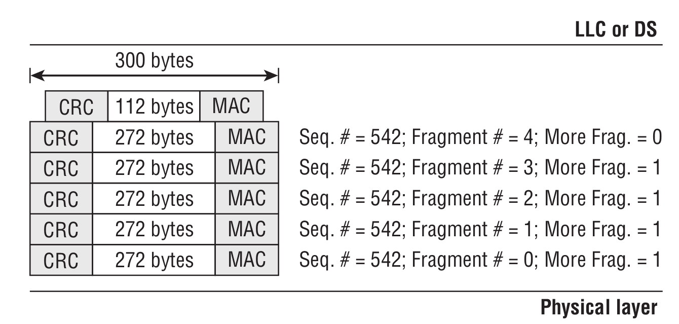
As can be seen from the picture, the Sequence Control field is divided into the Fragment Number and Sequence Number subfields. Sequence Number is a 12-bit subfield indicating the sequence number of an MSDU, A-MSDU, or MMPDU frame. Fragment Number indicates the number of each fragment of an MSDU or MMPDU frame. To get a better understanding of the function performed together by the Sequence Number and Fragment Number subfields, see the picture below.
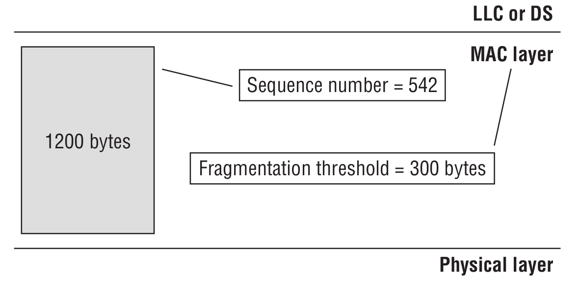
We need to transmit a data unit (MSDU) of 1200 bytes, but the access point is configured with a fragmentation threshold of 300 bytes (i.e. the frame size cannot exceed 300 bytes). The transmission of the data unit looks as follows:
QoS Control
This is a 16-bit field that identifies the Quality of Service (QoS) parameter of a data frame.
HT Control
The 802.11n standard adds a 4-byte HT Control field to the 802.11 MAC header. The HT Control field is present only in QoS Data and Management frames as determined by the Order bit in the Frame Control field.
Body
The Body field contains higher-level protocol data.
[xakepcut]
Frame subtypes
As promised earlier, we are now going to discuss subtypes of Control, Management, and Data frames in more detail.
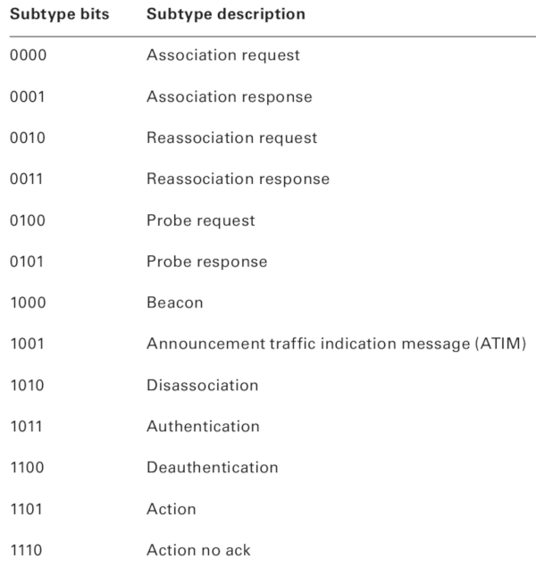
Management frame
In concordance with its name, this frame type constitutes the ‘skeleton’ of a wireless network.
Beacon Frame

Beacon frames are mostly used by access points and stations in the IBSS mode, such as when you are trying to create an ad hoc network, e.g. set up a direct wireless connection between your smartphone and laptop without an access point. By transmitting Beacon frames, the access point announces its presence and provides characteristics of the connection offered to the cell members (including SSID, frequency channel, timestamp field that tells the time at which the packet was sent from the transmitting node, supported rates, QoS capability, etc.).
Probe Request Frame
Every time you turn on Wi-Fi on your smartphone to connect to a wireless network, Probe Requests are sent to the broadcast DA address (ff:ff:ff:ff:ff:ff).
Probe Response Frame
Upon receiving a Probe Request, the access point or client device sends a Probe Response frame in the IBSS mode. The format of Probe Response is similar to the Bacon frame and contains information elements requested by the probing station and required to establish the connection.
Authentication Frame

Association request

The frame contains information on the radio card of the device (e.g. supported data transfer rates) and the SSID of the WLAN the device wants to be associated with. Upon receiving an Association Request, the access point makes a decision whether to associate with this radio card or not. If the decision is positive, the access point reserves memory and creates an Association Identifier (AID) for this radio card (i.e. for the user’s device).
Association response

Disassociation Frame

The DA field may contain the specific address of the client to be dissociated, or a broadcast address if all stations have to be disassociated from the AP. However, a dissociated STA still remains authenticated at the access point. This frame is used when the AP or client have to change the communication parameters.
Deauthentication Frame
The format of the Deauthentication frame is similar to that of the Disassociation frame. The AP sends it when all communications with a client have to be terminated. The Deauthentication and Disassociation frames can be distinguished by the Subtype field. For instance, the above-mentioned ESP8266 chip supports Deauther attacks. For more info, see ESP8266 Deauther 2.0 or Wi-PWN.
Reassociation Request Frame

Only clients can send Reassociation Request frames to the access point. This happens when the STA is already associated to the Extended Service Set (ESS) and wants to associate to another AP connected to the same ESS.
Control frame
Unlike Management and Data frames, Control frames do not have the Body field. The main Control frame subtypes are shown below.

RTS/CTS Frames
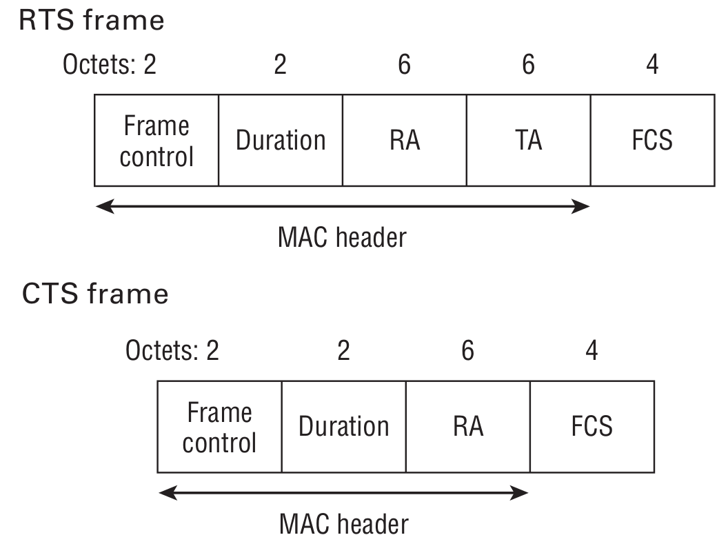
RTS (Request to Send) and CTS (Clear to Send) frames are used to enhance the communication between the STA and AP. Imagine that the access point is located next to a capital wall. You are surfing the Internet on your smartphone, while your friend uses a laptop at the far end of the apartment. Both your devices see the access point but cannot hear each other’s radio signals. To make sure that both of you can read Hacker articles, your devices use these frames.
A mobile device sends an RTS frame to another device; this is the first phase of the two-stage process required to send a data frame. A CTS received in response specifies the time for other stations to ‘keep silence’.
Acknowledgement Frame

Our world is not ideal. Any radio transmission is subject to electromagnetic interference. The recipient generates this frame after checking the received Data frame for errors.
Block Acknowledgement Request

The purpose of this frame is to enhance/expedite the data transmission by acknowledging multiple frames (blocks of frames) at once. Prior to using this feature, it is necessary to make sure that the recipient supports it.
- RA is the MAC address of the recipient.
- TA is the MAC address of the station sending the BlockAck-Req frame.
Block Acknowledgement

A frame generated to acknowledge the receipt of several QoS Data frames instead of acknowledging each of them separately.
- RA is the MAC address of the station requesting the Block Ack frame.
- TA is the MAC address of the device sending the Block Ack frame.
PS-Poll

When a STA in the Power Save mode receives a Beacon, it checks whether its AID is set in the TIM (i.e. the AP has some data to be sent to the client). In that situation, the STA sends a PS-Poll to the AP, thus, indicating that it is ready to receive the buffered data.
- BSSID (RA) is the MAC address of the access point the client is connected to.
- TS is the MAC address of the client who has generated the PS-Poll.
Control Wrapper

The 802.11n standard defines the Control Wrapper as a frame used to carry any other control frame, other than another Control Wrapper frame, together with the HT Control field.
Contention Free

Both frames are used to indicate the end of the contention-free period (CFP). In the second case, an acknowledgment frame is required.
Data Frame
Taking the large number of Control frame subtypes, you won’t be surprised to hear that there are 15 different Data frame subtypes.

As you can see, Data frames can be divided into two large categories: Data frames containing data and Data frames, well, not containing data. A logical question is: what is the purpose of Data frames that do not contain data? In fact, sometimes it is necessary to transmit service information to the access point or other device connected to the network. For instance, devices may use Null data frames to activate or end the Power Save mode.
Now it is a good time to mention the frame fragmentation possibility.

On the one hand, this increases the overhead, but on the other hand, should any collision occur, we have to retransmit not the entire jumbo frame, but only a small portion of it, thus increasing the bandwidth.
The icing on the cake is the fact that the 802.11 standard supports the transmission of A-MSDUs (aggregate MAC service data units) and A-MPDUs (aggregate MAC protocol data units). Here are a few definitions.
As said above, MSDU is a payload containing an IP packet + some LLC data. MPDU is a 802.11 frame; while PLCP is the physical layer convergence procedure. The A-MSDU frame aggregation scheme looks as follows:
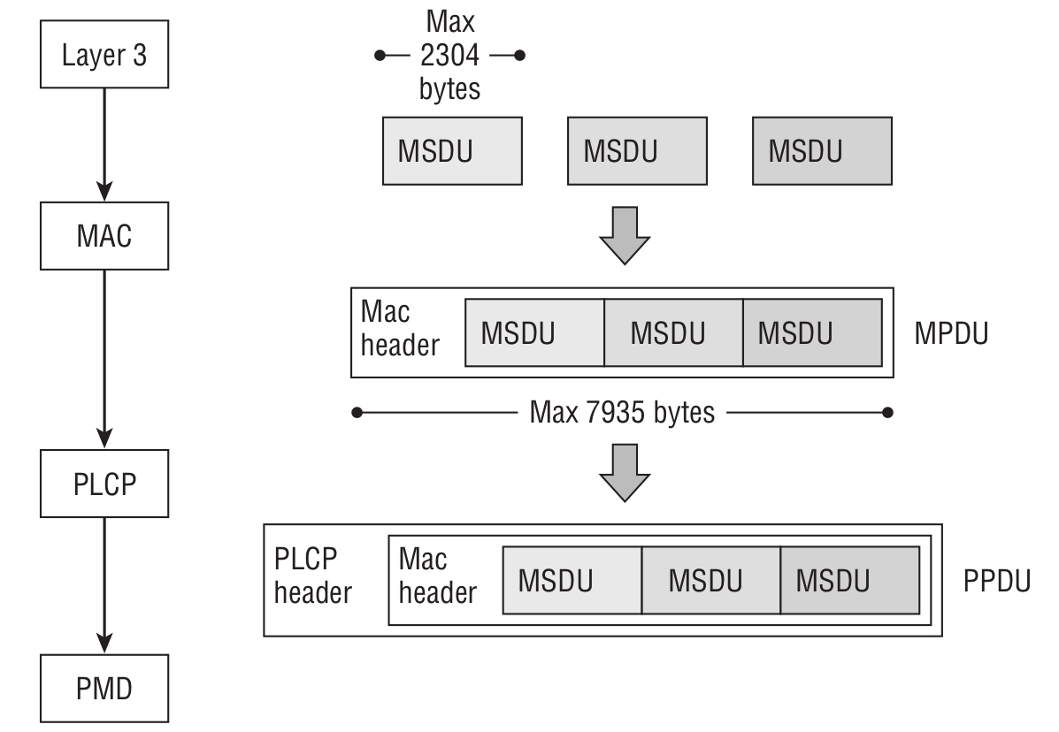
If encryption is enabled, then all MSDUs are encrypted together as a single payload. It is necessary to keep in mind that an A-MSDU shall contain only MSDUs whose DA and SA parameter values map to the same RA and TA values.
Below is the A-MPDU frame aggregation scheme:
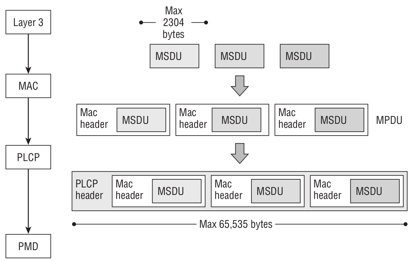
The difference is that if encryption is enabled, then each MPDU is encrypted individually. In addition, individual MPDUs within an A-MPDU must all have the same receiver address.
For those willing to get a better understanding of the 802.11 standard, I would recommend (aside from the IEEE 802.11 documentation) My CWAP Study Notes and this resource. The books below are useful as well:
- CWAP Certified Wireless Analysis Professional Official Study Guide Exam PW0-270; and
- CWAN Certified Wireless Network Administrator Official Study Guide Exam PW0-105.
Practical section
Now that we have successfully got through the details and nuances of the 802.11 standard, it is time to build the sniffer. Let us start with the goal identification.
What do we need?
- First of all, we need a simple connection to our PC/laptop, i.e. a USB socket. Not all laptops have Ethernet/LAN sockets, and not every Wi-Fi card allows you to switch it to the promiscuous mode. Here is the list of network cards supporting this mode.
- Second, we want to be able to dynamically switch between channels and need a flexible filter for incoming packets (to monitor only Control frames or Data frames with a specific MAC or IP address).
- At the initial stage of the packet analysis: if we have received a complete packet, it should go to the computer. However, if this is a fragmented packet or a part of an aggregated packet, the sniffer should wait until the other components are received, aggregate the packet, and only then send it to the computer.
- Of course, we want wireshark to display the monitored traffic in real time.
- One more requirement: if we know the password to a Wi-Fi network were are sniffing, it would be great to have a magic function -something like
decrypt_message(* ptr_message, *WPA_WPA2_key)– decrypting the data for subsequent analysis.
Unlike the ESP8266, EPS32 has a configurable hardware buffer to receive and send 802.11 frames. We can change the number of the buffers; the size of each buffer is 1600 bytes, which is enough to store a frame. My experiments have shown that the buffer size of 1600 bytes is sufficient to monitor a Wi-Fi network. However, it is necessary to keep in mind an important feature: EPS32 (to be specific, the driver supplied with the SDK) can dump to the application only the following frame types in the promiscuous mode:
- 802.11 Management frame;
- 802.11 Data frame, including MPDU, AMPDU, AMSDU, etc; and
- 802.11 MIMO frame, for MIMO frame, the sniffer only dumps the length of the frame.
The following packets will NOT be dumped to the application:
- 802.11 Control frame; and
- 802.11 Error frame, such as the frame with a CRC error, etc.
In my opinion, it’s not a big deal that ESP32 cannot catch all frame types: in addition to monitoring the incoming frames, we can send some data as well using esp_wifi_80211_tx function. However, there are some restrictions: so far, we may only send Beacon/Probe Request/Probe Response/Action, and non-QoS data frames.
In order to initialize Wi-Fi, set the promiscuous mode, and sniff Wi-Fi traffic, we use the following piece of code provided with the SDK:
wifi_init_config_t cfg = WIFI_INIT_CONFIG_DEFAULT();
wifi_country_t wifi_country = {
  .cc="CN",
  .schan=1,
  .nchan=13,
  .policy=WIFI_COUNTRY_POLICY_AUTO
};
nvs_flash_init();
tcpip_adapter_init();
ESP_ERROR_CHECK(esp_event_loop_init(event_handler, NULL));
ESP_ERROR_CHECK(esp_wifi_init(&cfg));
ESP_ERROR_CHECK(esp_wifi_set_country(&wifi_country));
ESP_ERROR_CHECK(esp_wifi_set_storage(WIFI_STORAGE_RAM));
ESP_ERROR_CHECK(esp_wifi_set_mode(WIFI_MODE_NULL));
ESP_ERROR_CHECK(esp_wifi_start());
ESP_ERROR_CHECK(esp_wifi_set_channel(WIFI_CHANNEL, WIFI_SECOND_CHAN_NONE));
ESP_ERROR_CHECK(esp_wifi_set_promiscuous_rx_cb(&sniffer_wifi));
The last line sets the function sniffer_wifi to be called every time after the capture of a new frame.
I use ESP32-PICO-KIT V4; out of the box, it can be connected to USB via an UART to USB adapter on the CP2102 chip. Therefore, we have to initialize and set up the UART interface:
uart_config_t uart_cfg = {
  .baud_rate = UART_2_PC_BAUD_RATE,
  .data_bits = UART_DATA_8_BITS,
  .parity    = UART_PARITY_DISABLE,
  .stop_bits = UART_STOP_BITS_1,
  .flow_ctrl = UART_HW_FLOWCTRL_DISABLE
};
ESP_ERROR_CHECK(uart_param_config(UART_2_PC, &uart_cfg));
ESP_ERROR_CHECK(uart_set_pin(UART_2_PC,
  UART_PIN_NO_CHANGE,
  UART_PIN_NO_CHANGE,
  UART_PIN_NO_CHANGE, UART_PIN_NO_CHANGE));
ESP_ERROR_CHECK(uart_driver_install(UART_NUM_0, 4096, 0, 0, NULL, 0));
The SDK allows us to configure filters so that we catch only certain frame types.
wifi_promiscuous_filter_t filter = {
  .filter_mask = WIFI_PROMIS_FILTER_MASK_DATA
};
ESP_ERROR_CHECK(esp_wifi_set_promiscuous_filter(&filter));
Below is the complete list of packets that can be filtered:
// filter all packets
#define WIFI_PROMIS_FILTER_MASK_ALL           (0xFFFFFFFF)
// filter the packets with type of WIFI_PKT_MGMT
#define WIFI_PROMIS_FILTER_MASK_MGMT          (1)
// filter the packets with type of WIFI_PKT_CTRL
#define WIFI_PROMIS_FILTER_MASK_CTRL          (1<<1)
// filter the packets with type of WIFI_PKT_DATA
#define WIFI_PROMIS_FILTER_MASK_DATA          (1<<2)
// filter the packets with type of WIFI_PKT_MISC
#define WIFI_PROMIS_FILTER_MASK_MISC          (1<<3)
// filter the MPDU which is a kind of WIFI_PKT_DATA
#define WIFI_PROMIS_FILTER_MASK_DATA_MPDU     (1<<4)
// filter the AMPDU which is a kind of WIFI_PKT_DATA
#define WIFI_PROMIS_FILTER_MASK_DATA_AMPDU    (1<<5)
// filter all control packets
#define WIFI_PROMIS_CTRL_FILTER_MASK_ALL      (0xFF800000)
// filter the control packets with subtype of Control Wrapper
#define WIFI_PROMIS_CTRL_FILTER_MASK_WRAPPER  (1<<23)
// filter the control packets with subtype of Block Ack Request
#define WIFI_PROMIS_CTRL_FILTER_MASK_BAR      (1<<24)
// filter the control packets with subtype of Block Ack
#define WIFI_PROMIS_CTRL_FILTER_MASK_BA       (1<<25)
// filter the control packets with subtype of PS-Poll
#define WIFI_PROMIS_CTRL_FILTER_MASK_PSPOLL   (1<<26)
// filter the control packets with subtype of RTS
#define WIFI_PROMIS_CTRL_FILTER_MASK_RTS      (1<<27)
// filter the control packets with subtype of CTS
#define WIFI_PROMIS_CTRL_FILTER_MASK_CTS      (1<<28)
// filter the control packets with subtype of ACK
#define WIFI_PROMIS_CTRL_FILTER_MASK_ACK      (1<<29)
// filter the control packets with subtype of CF-END
#define WIFI_PROMIS_CTRL_FILTER_MASK_CFEND    (1<<30)
// filter the control packets with subtype of CF-END+CF-ACK
#define WIFI_PROMIS_CTRL_FILTER_MASK_CFENDACK (1<<31)
It can be found in the file esp_wifi_types.h.
[panel]
Epistolary genre
I wrote an extensive letter to the technical support team of Espressif Systems asking to enhance the Wi-Fi-related functionality of the SDK and make it possible to receive and send 802.11 frames without any limitations. They promised to consider it and to include my requests in the development plan. Therefore, if you would like the ESP32 chip to gain some new exciting features (e.g. ability to receive and send all types of 802.11 frames, USB 2.0 onboard, support of 5 GHz, and magic_function enabling it to decrypt captured data provided that the Wi-Fi password is known), you may visit the forum thread What would you like to see in The Next Chip? and express your wishes. Should you have more ideas about the next iteration of ESP32, do not hesitate to share your desires with the developers.
[/panel]
In addition, the file esp_wifi_types.h contains a useful structure:
wifi_pkt_rx_ctrl_t:
typedef struct {
  // Received Signal Strength Indicator(RSSI) of packet. unit: dBm
  signed rssi:8;
  // PHY rate encoding of the packet. Only valid for non HT(11bg) packet
  unsigned rate:5;
  unsigned :1; // reserve
  unsigned sig_mode:2; // 0: non HT(11bg) packet; 1: HT(11n) packet; 3: VHT(11ac) packet
  unsigned :16; // reserve
  // Modulation Coding Scheme. If is HT(11n) packet, shows the modulation, range from 0 to 76(MSC0 ~ MCS76)
  unsigned mcs:7;
  // Channel Bandwidth of the packet. 0: 20MHz; 1: 40MHz
  unsigned cwb:1;
  unsigned :16; // reserve
  unsigned smoothing:1; // reserve
  unsigned not_sounding:1; // reserve
  unsigned :1; // reserve
  // Aggregation. 0: MPDU packet; 1: AMPDU packet
  unsigned aggregation:1;
  // Space Time Block Code(STBC). 0: non STBC packet; 1: STBC packet
  unsigned stbc:2;
  // Flag is set for 11n packets which are LDPC
  unsigned fec_coding:1;
  // Short Guide Interval(SGI). 0: Long GI; 1: Short GI
  unsigned sgi:1;
  // noise floor of Radio Frequency Module(RF). unit: 0.25dBm
  signed noise_floor:8;
  // ampdu cnt
  unsigned ampdu_cnt:8;
  // primary channel on which this packet is received
  unsigned channel:4;
  // secondary channel on which this packet is received. 0: none; 1: above; 2: below
  unsigned secondary_channel:4
  unsigned :8; // reserve
  // timestamp. The local time when this packet is received. It is precise only if modem sleep or light sleep is not enabled. unit: microsecond
  unsigned timestamp:32;
  unsigned :32; // reserve
  unsigned :31; // reserve
  // antenna number from which this packet is received. 0: WiFi antenna 0; 1: WiFi antenna 1
  unsigned ant:1;
  // length of packet including Frame Check Sequence(FCS)
  unsigned sig_len:12;
  unsigned :12; // reserve
  // state of the packet. 0: no error; others: error numbers which are not public
  unsigned rx_state:8;
} wifi_pkt_rx_ctrl_t;
This structure is accessible every time the callback is triggered indicating that a new frame is available. As you can see, the file contains plenty of helpful information that can be used for packet processing.
One might say: “We are sniffing a 802.11n Wi-Fi network with a bandwidth of up to 600 MBps while our debug board is connected to the PC via a humble UART interface with a standard baud rate of 115 200, which is lower than the Wi-Fi speed. So, how can we monitor this network?”
- First, the experience shows that the debug board supports the rate of 921 600 baud.
- Second, if we replace the UART-USB adapter with a newer CP2102N chip, then the data transfer rate can be increased to 3 MBaud.
- Third, Espressif Systems officially states that “The UART interface of ESP32 can work on 5Mbps band rate”.
- And finally, we can set up filters to capture only certain packet types.
In the course of my experiments, I managed to get continuous data flows for some periods of time. Still, there is a spoon of tar in the barrel of honey: the debug board runs hot. You cannot make scrambled eggs on it, but the board is not cool at all. On the other hand, the cost of such a debug board is only about $10.
Battle testing
An access point with a simple web server was launched on the first ESP32. At the initial stage, I turned the encryption off. Then I connected to this AP from my laptop and started pinging. The sniffer has been launched on the second ESP32.

As a result of the sniffer’s work, the following packet is displayed

Let us figure out what do these bytes mean:
[panel template=term]
MAC HEADER -> FC: 88 02
MAC HEADER -> Duration/ID 30 00
MAC HEADER -> Address1 11 22 33 44 55 66
MAC HEADER -> Address2 AA BB CC DD EE FF
MAC HEADER -> Address3 AA BB CC DD EE FF
MAC HEADER -> SEQUENCE CTRL 90 2F
MAC HEADER -> QOS 00 00
[/panel]
Then the LLC & SNAP Header comes into play: AA AA 03 00 00 00 08 00. I suppose that you have already recognized in the LLC & SNAP Header, starting from 08 00, an important command: ping. The last four bytes are the control sum.
[panel]
Acknowledgments
I am grateful to a colleague for assistance in my project, including setup of the СС3220SF-based debug board, CC3220SF-LAUNCHXL. On the one hand, this microcontroller is not very powerful: a humble 80 MHz Cortex-M4 and only 256 KB of RAM (against 240 MHz Xtensa LX6 C and 520 KB of RAM featured by ESP32). However, according to this wiki, it can be switched to the promiscuous mode enabling us to receive all 802.11 frames and send raw packets.
In addition to such a flexibility in receiving and sending 802.11 frames, the board features a flexible filtering system for incoming packets:

In other words, СС3220SF makes it possible to implement the following features described in CC3120, CC3220 SimpleLinkTM Wi-Fi ® and Internet of Things Network Processor Programmer’s Guide (chapter 10.3.2):
- Receive WLAN data broadcast frames only from two specific MAC addresses.
- Do not receive WLAN unicast frames from a certain SRC_IP address range.
- If a unicast frame is received from MAC address AA.BB.CC.DD.EE.FF, increase counter_1.
- If a unicast frame is received from MAC address CC.HH.II.JJ.KK.LL, increase counter_2.
- If a unicast UDP frame is received from MAC address AA.BB.CC.DD.EE.FF or CC.HH.II.JJ.KK.LL, * pass only packets from port 5001.
[/panel]
Conclusions
Of course, my project did not make any revolution; furthermore, at some points, I had reinvented the wheel because ESP32-based sniffers already exist, including ArduinoPcap, ESP32-WiFi-Sniffer, and a project of Espressif Systems. But I still like the result. Each solution has its strengths and weaknesses, and you can customize your device to ensure that it complies with your goals and objectives in the best way possible.
[panel template=www]
The current state of the project can be checked here.
[/panel]


