It all started when, some time ago, I built myself a phone around a GSM module. I put modern electronics into a vintage case with an external handset and a rotary dial (do you even remember how to use one?). Unfortunately, due to a flawed design, making calls on it was awkward.
So I decided to make a second attempt, but with a new concept. I wanted a compact device that works like a basic feature phone with physical buttons and is practical for real-world use. Ideally, even a small battery should last at least a week. No extra services, shady apps, or annoying notifications—just the essentials: calls, SMS, and a contacts list.

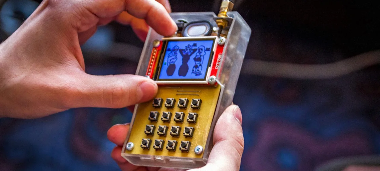
The project was showcased at Chaos Constructions 2019 and, to my pleasant surprise, it attracted a lot of interest from a broad audience. Many people were curious about the inner workings of a mobile phone, so today I’ll explain in detail how you can build a similar gadget yourself.
warning
Unfortunately, the cellular system by design allows carriers to track subscribers in near real time with roughly 20-meter accuracy (by triangulating against multiple base stations). Given Russia’s practice of tying SIM registration to passport IDs, the picture isn’t great. It is possible to evade carrier monitoring, but those methods are beyond the scope of this article.
Component Block Diagram
First, let’s define the device requirements: we need to place outgoing calls, receive incoming calls, read and send SMS (including Cyrillic), and manage contacts in the address book. That’s the baseline functionality users expect from feature phones. Of course, this isn’t an exhaustive list—at the very least we’re missing built-in games like Snake or Tetris—but those can be added at the final stage.
The core of the device will be the SIM800C cellular module. It includes a complete RF front end, an audio path, and implements the essential GSM network functions. In other words, it’s essentially a ready-made GSM–UART bridge that only needs to be controlled by an external terminal.
We’ll need a display, a keyboard, and a microcontroller to run the main program. For the display I used an ST7735 module with a 128×160 resolution. I already had a library for it that could render text and basic graphic primitives. Overall, the display choice isn’t critical—you can use any other screen with a suitable diagonal.
A 16‑key keypad is built on shift registers (a pair of 8‑bit 74HC165 ICs PDF). You can also use their domestic counterpart, the KR1533IR9 from Integral. In any case, the outputs of these registers don’t form a proper SPI interface, since even when deselected they don’t go into a high‑impedance state. Therefore, instead of the hardware SPI bus shared with the display, a software (bit‑banged) implementation was used.
The system is driven by an STM32 family microcontroller. Since there are no tight performance requirements, even budget parts are sufficient. I went with the F103C8T6 (PDF), which has resources to spare for this job. It’s also the MCU used in the well-known BluePill dev board lineup—a great way to kick the Arduino habit—so I was able to spin up a prototype and start testing components almost immediately.
info
Some F103C8T6 chips have 128 KB of memory instead of the 64 KB stated in the documentation. However, this falls under undocumented features, so you shouldn’t count on that “extra” memory bank.
Later (as a nice bonus), I decided to add a 32‑Mbit W25Q32 external non‑volatile memory chip (PDF). This let me avoid rewriting the microcontroller’s own flash and store all contacts separately. It also enabled uploading images, glyphs, and other raster graphics to the phone.
The phone section of the schematic is fairly standard and needs little explanation. The SIM800C is brought up by driving its RST pin low (using transistor Q1 connected to the microcontroller’s PA0 pin). Additionally, LEDs VD2 and VD3 indicate the radio module’s status: VD2 blinks when a connection is established, while VD3 stays lit as long as the SIM800C is active.

The components are laid out on two single-sided PCBs, mostly using surface-mount parts. The first board hosts the radio module, microcontroller, external memory IC, and connectors for the antenna and speaker. The second board is dedicated entirely to the keyboard. The assembled unit is housed in an acrylic (plexiglass) case and mounted on M3 standoffs.
Our device is powered by a 1,500 mAh lithium‑polymer battery. Its capacity is roughly half that of modern flagship smartphones, but it still provides about a week in standby (around 6 mA draw) or a full day of active use (around 40 mA draw).
info
Generally speaking, most of the electronic components used are now available as off-the-shelf evaluation boards or modules. So if you don’t want to deal with PCB layout and soldering ICs, you can assemble everything on solderless breadboards.
Configuring the UART
There’s no shortage of ways to program microcontrollers today. You can choose from several languages (C/C++, Rust) and a variety of libraries and frameworks that abstract away the hardware details (STMicroelectronics’ HAL, Arduino Core, and others). For this project, I used plain C and the open-source libopencm3.
www
The complete set of project source files is available in the repository on GitHub.
First, initialize UART1, since it handles communication with the radio module. Use the standard settings: 115,200 baud, 8N1.
static void usart1_setup(void){
    /* Enable clocks for GPIO port A (for GPIO_USART1_TX) and USART1 */
    rcc_periph_clock_enable(RCC_GPIOA);
    rcc_periph_clock_enable(RCC_USART1);
    /* Enable the USART1 interrupt */
    nvic_enable_irq(NVIC_USART1_IRQ);
    /* PA9 TX,PA10 RX */
    gpio_set_mode(GPIOA, GPIO_MODE_OUTPUT_50_MHZ, GPIO_CNF_OUTPUT_ALTFN_PUSHPULL, GPIO_USART1_TX);
    gpio_set_mode(GPIOA, GPIO_MODE_INPUT, GPIO_CNF_INPUT_FLOAT, GPIO_USART1_RX);
    /* Setup UART parameters */
    usart_set_baudrate(USART1, 115200);
    usart_set_databits(USART1, 8);
    usart_set_stopbits(USART1, USART_STOPBITS_1);
    usart_set_mode(USART1, USART_MODE_TX_RX);
    usart_set_parity(USART1, USART_PARITY_NONE);
    usart_set_flow_control(USART1, USART_FLOWCONTROL_NONE);
    usart_enable_rx_interrupt(USART1);
    usart_enable(USART1);
}
After that, it makes sense to set up a way to send commands to the module—for example, by using a third-party implementation of printf(). The rprintf library works well for this. Its code is well optimized and takes only a few kilobytes of memory. You’ll need to tweak the library to work with libopencm3—just a few lines of changes.
#38  #define UART USART1
...
#95  vfprintf_((&usart_send_blocking), format, arg);
...
#142 ch = usart_recv_blocking(UART);
You can now send commands to the module using printf_(, and the module’s response is received via interrupts and stored in a buffer. After reception, the content is parsed, and if it matches the expected response, a handler function is invoked to display SMS and USSD messages. It’s also possible to print the message directly to the screen, which is very convenient for debugging.
Working with the Display
Like any other peripheral, the display needs to be initialized before use. Sure, you can find suitable code online, but I decided to write my own implementation. It won’t take long and it’s a good way to get familiar with the ST7735 controller. I relied on the manufacturer’s documentation (PDF) and used the provided pseudocode examples as a starting point.
static void spi1_setup(void){
    /* Enable SPI1 Periph and gpio clocks */
    rcc_periph_clock_enable(RCC_SPI1);
    rcc_periph_clock_enable(RCC_GPIOA);
    /* Configure GPIOs:
      * SCK = PA5
      * DC = PA6
      * MOSI = PA7
      * CS = PA1
      * RST = PA4
      * LED = PB0
      */
    gpio_set_mode(GPIOA, GPIO_MODE_OUTPUT_50_MHZ, GPIO_CNF_OUTPUT_ALTFN_PUSHPULL, GPIO5 | GPIO7);
    gpio_set_mode(GPIOA, GPIO_MODE_OUTPUT_50_MHZ, GPIO_CNF_OUTPUT_PUSHPULL, GPIO4 | GPIO6 | GPIO1);
    /* Reset SPI, SPI_CR1 register cleared, SPI is disabled */
    spi_reset(SPI1);
    /* Set up SPI in Master mode with:
      * Clock baud rate: 1/64 of peripheral clock frequency
      * Clock polarity: Idle High
      * Clock phase: Data valid on 2nd clock pulse
      * Data frame format: 8-bit
      * Frame format: MSB First
      */
    spi_init_master(SPI1, SPI_CR1_BAUDRATE_FPCLK_DIV_2, SPI_CR1_CPOL_CLK_TO_0_WHEN_IDLE, SPI_CR1_CPHA_CLK_TRANSITION_1, SPI_CR1_DFF_8BIT, SPI_CR1_MSBFIRST);
    /* Set NSS management to software */
    spi_enable_software_slave_management(SPI1);
    spi_set_nss_high(SPI1);
    /* Enable SPI1 periph. */
    spi_enable(SPI1);
    gpio_set(GPIOA, GPIO1);
}
The library provides functions for drawing points, lines, and circles, printing characters and entire strings, and refreshing the display. It also supports rendering Cyrillic characters in the CP866 encoding. The key entry point is the st7735_sendchar(char* c) call, which lets you stream strings to the display, including control sequences. Currently supported control characters are newline (\n), carriage return (\r), clear screen (\a), and backspace (\b).
void st7735_sendchar(char ch){
    uint16_t px, py;
    gpio_clear(STPORT, STCS);
    if (ch == '\r') {
        pos -= pos % 26;
        return;
    }
    if (ch == '\n') {
        pos += 26;
        pos -= pos % 26;
        return;
    }
    if (ch == '\a') {
        pos = 0;
        st7735_clear(bg_color);
        return;
    }
    if (ch == '\b') {
        pos--;
        px = (pos % 26) * 6;
        py = (pos / 26) * 8;
        st7735_drawchar(px, py, 0x20, txt_color, bg_color);
        return;
    }
    if(pos > 416) {
        pos=0;
        st7735_clear(bg_color);
    }
    px = (pos % 26) * 6;
    py = (pos /26) * 8;
    st7735_drawchar(px, py, ch, txt_color, bg_color);
    pos++;
    while (SPI_SR(SPI) & SPI_SR_BSY);
    gpio_set(STPORT,STCS);
}
By default, it uses green text on a black background. You can set the colors explicitly by calling the function st7735_set_printf_color(. In addition, there is a helper function to display the character the user is currently typing on the keyboard.
void st7735_virt_sendchar(char ch){
    uint16_t px, py;
    gpio_clear(STPORT, STCS);
    px = (pos % 26) * 6;
    py = (pos / 26) * 8;
    if (ch > 0x20)  {
        st7735_drawchar(px, py, ch, RED, bg_color);
    }
    while (SPI_SR(SPI) & SPI_SR_BSY);
    gpio_set(STPORT, STCS);
}
It’s similar to st7735_sendchar(, but it doesn’t process control sequences and doesn’t update the current cursor position. Therefore, calling st7735_sendchar( after st7735_virt_sendchar( will redraw on the screen the character output by st7735_virt_sendchar(.
Keypad
The whole keypad is connected via shift registers to a software SPI bus. User input is handled by the 4х4key library. The keyboard has two layouts—Russian and English—with four characters assigned to each key in each layout.
Here I deviated a bit from the classic 2000s keypad phones: selecting a character is based on how long you hold the key, not how many times you press it. The reason is that old mobiles typically used membrane keypads, whereas tact switches are stiffer, so cycling through letters with repeated presses isn’t as convenient.
Let’s take a closer look at the input handling process. The get_key( function is responsible for polling the keyboard. It uses the read_key(, routine, which reads the current state of the shift registers and returns two bytes of key state data. Key combinations aren’t implemented at the moment, but they can be added easily if needed.
The layout switches when code 0x0002 is received; otherwise, the character code is returned. Depending on the selected language, the ch_map variable is incremented.
...
while (!key_code) {
    key_code = read_key();
}
do {
    if(key_code == 0x0002) {
        if (ch_map < 2) {
            ch_map++;
        else {
            ch_map = 0;
        }
        show_char_map(ch_map);
        while(key_code==2) key_code=read_key();
    }
    while(!key_code) {
        key_code = read_key();
    }
} while (key_code == 0x0002);
...
Next, the key_map() function is called, which takes the key code and the current layout index as inputs. It looks up the corresponding character in the char_map array and returns it. The subsequent input handling logic depends on the character obtained.
...
if (key == '\n') {
    delay(500);
} else if (key == '\b') {
    delay(500);
} else if(key == ' ') {
#ifdef ECHO
    st7735_virt_sendchar(key);
#endif
    delay(800);
    timer_start();
    old_keycode = key_code;
    do {
        key_code = read_key();
        if (key_code){
            if (key_code == old_keycode) {
                count++;
                if (count > 15) {
                    count = 0;
                }
                wait_key_counter = 0;
            } else {
                count = 0;
                break;
            }
            key = keymap2(count, 2);
#ifdef ECHO
            systick_interrupt_disable();
            st7735_virt_sendchar(key);
            systick_interrupt_enable();
#endif
            delay(900);
    }
} while (wait_key_counter < 1000);
timer_stop();
...
The keypad handler ended up more complex than I wanted, but I managed to map almost all the necessary characters onto sixteen keys, which is pretty convenient. Still, there are cases where I need an immediate response to key presses—for example, when triggering menu items or answering an incoming call. For that, I implemented a separate function, fast_get_key(, which works with a reduced character set.
char fast_get_key() {
    uint16_t key_code;
    char key;
    while (!key_code) {
        key_code=read_key();
    }
    key = keymap(key_code, 0);
    while (read_key()) {
         __asm__("nop");
    }
#ifdef ECHO
    echo(key);
#endif
    return key;
}
Now that we have a display and a keyboard, the only pieces left to turn it into a terminal are stprintf( and kscanf(. We implemented them using the previously mentioned rprintf library, though this part required a few more tweaks.
int stprintf(const char \*format, …) {
    va_list arg;
    va_start(arg, format);
    stprintf_((&st7735_sendchar), format, arg);
    va_end(arg);
    return 0;
}
The kscanf( function is a bit trickier, because we currently have two routines for reading a character from the keyboard. So we’ll need to unify them behind a single interface that can switch between get_key( and fast_get_key(. While we’re at it, we’ll also add support for the control character \ (Backspace).
void set_scanf_mode(unsigned char mode) {
    fast_mode=mode;
}
int kscanf(const char* format, …) {
    va_list args;
    va_start( args, format );
    int count = 0;
    char ch = 0;
    char buffer[kscanf_buff_size];
    kscanf_buffer = buffer;
    while (count <= kscanf_buff_size ) {
        if(fast_mode) {
            ch = fast_get_key();
        } else {
            ch = get_key();
        }
        if (ch == '\b') {
            if (kscanf_buffer > buffer) {
                kscanf_buffer--;
            }
            continue;
        } else {
            count++;
        }
        if (ch != '\n' && ch != '\r') {
            *kscanf_buffer++ = ch;
        else {
            break;
        }
    }
    *kscanf_buffer = '\0';
    kscanf_buffer = buffer;
    count =  ksscanf(kscanf_buffer, format, args);
    va_end(args);
    return count;
}
So, we’ve implemented the I/O system and now have a nearly full‑featured terminal. For example, to clear the screen and print the classic greeting, just write a single line:
stprintf("\aHello World!");
GSM Module
Let’s look at working with the SIM800 using an SMS-sending example; the other functions behave similarly. We’ll use text mode because it’s more straightforward. Additionally, to send messages in Cyrillic, you need to configure the encoding beforehand.
void sim800_init_cmd() {
    printf_("AT+CMGF=1\r\n");
    for (uint32_t i = 0; i < 0xFFFFFF; i++) __asm__("nop");
    printf_("AT+CSCS="UCS2"\r\n");
    for (uint32_t i = 0; i < 0xFFFFFF; i++) __asm__("nop");
    printf_("AT+CSMP=17,167,0,8\r\n");
    for (uint32_t i = 0; i < 0xFFFFFF; i++) __asm__("nop");
}
void fast_sms_send(char *text, char *tel) {
    char *p_tel;
    char u_tel[64]="+7";
    char temp[512];
    if (tel[0] == '8') {
        p_tel = tel + 1;
    } else if (tel[0] == '+') {
        p_tel = tel + 2;
    } else {
        p_tel = tel;
    }
    strcat(u_tel, p_tel);
    strcpy(temp, text);
    cp866_to_utc2(temp);
    cp866_to_utc2(u_tel);
    stprintf("\aSend sms\r\nAT+CMGS="%s"\r\n%s\x1A", u_tel, temp);
    printf_("AT+CMGS="%s"\r\n", u_tel);
    for (uint32_t i = 0; i < 0xFFFFFF; i++) __asm__("nop");
    printf_("%s\x1A", temp);
}
Now you can use something meaningful and easy to understand in your code, for example:
fast_sms_send("Hello world!", "89162402484");
Let’s try passing a Cyrillic string after enabling the appropriate encoding:
void write_sms() {
    char text[256];
    char tel[13];
    uint8_t ret_code;
    stprintf("\aSMS writer v0.01\r\n"
                    "Enter the sms text\r\n"
                    ">");
    kscanf("%s", text);
    ret_code = telbook_get_number(tel);
    if(!ret_code) {
        return;
    }
    fast_sms_send(text, tel);
}
By the way, the contact number here comes from a phonebook entry. I think it’s worth going into a bit more detail about that.
Contacts
As I mentioned, the contact information is stored in an external memory chip. Each record is 32 bytes: 16 for the phone number and 16 for the subscriber’s name. Right now the data are written in cleartext, without encryption. Ideally, you’d use AES or another block cipher here.
The phonebook’s core features let you retrieve a contact’s number (telbook_get_number(), as well as add or delete entries (telbook_rec_add( and telbook_rec_del(). You can also look up a name by phone number using telbook_find_name(. For low-level interaction with the memory chip, the 25q32 library handles all the hardware-specific details.
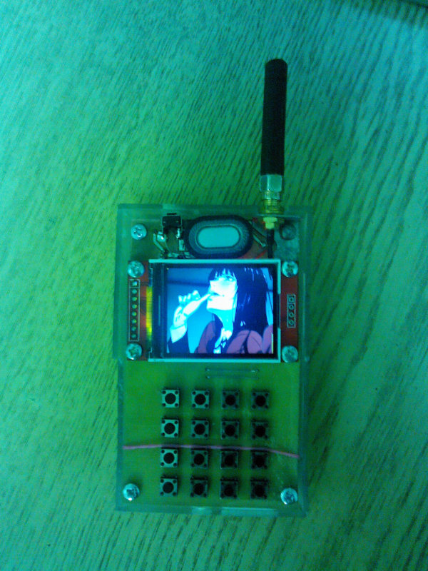
Working with Graphics
What else can you try when you’ve got a color display and a few megabytes of free memory? Naturally, show some images—that practically suggests itself. The phone easily handles BMP files at 128×160 resolution with 16-bit color. The images are stored in an external flash chip and rendered to the screen using the img_from_flash( function, which takes the start address of the pixel array. The format is very straightforward, and if you’ve forgotten the details, you can always read up on the header and offset in the internet.
The image is sent to the display in chunks using a stack-allocated buffer. On each pass, 4096 bytes are read from memory into the buffer and then pushed to the screen. You might note that the F103C8T6 has a DMA controller meant for exactly this kind of task. However, since we can’t statically allocate the entire frame buffer in memory, the benefit of using DMA here would be minimal.
void img_from_flash_v3(uint32_t addr) {
    uint8_t bufer[4096];
    gpio_clear(STPORT, STCS);
    st7735_sendcmd(ST7735_MADCTL);
    st7735_senddata(1 << 7);
    while (SPI_SR(SPI) & SPI_SR_BSY);
    gpio_set(GPIOA, STCS);
    for(uint8_t i = 0; i < 10; i++) {
        w25_read(addr + (i * 4096), bufer, 4096);
        st7735_drawimg(0,0+16*i,128,16, bufer);
    }
    gpio_clear(STPORT, STCS);
    st7735_sendcmd(ST7735_MADCTL);
    st7735_senddata(MV | MX);
    while (SPI_SR(SPI) & SPI_SR_BSY);
    gpio_set(STPORT, STCS);
}
Obviously, before you can access the images in memory, you first have to write them there. For that, I use UART2 and the XMODEM protocol. On the receiving side, the data is processed by the xmodem_to_flash() function, which takes the file’s start address in flash as its argument.
void xmodem_to_flash(uint32_t addr) {
    unsigned char buf[132];
    uint32_t byte = 0;
    uint8_t lastlen, ch;
    usart2_init();
    usart_send_blocking(USARTX, NAK);
    while(1){
        ch = usart_recv_blocking(USARTX);
        if (ch == SOH){
            for (uint8_t i = 0; i < 131; i++) {
                ch = usart_recv_blocking(USARTX);
                buf[i]=ch;
            }
            lastlen=129;
            while(buf[lastlen--] == EOF);
            lastlen -= 1;
            w25_write(addr + byte, buf + 2, lastlen);
            byte += lastlen;
            usart_send_blocking(USARTX,ACK);
            continue;
        }
        if (ch == EOT){
            usart_send_blocking(USARTX, ACK);
            break;
        }
    }
    usart2_deinit();
}
So, to write a file from the host PC, I start the transfer using a terminal program (for example, minicom), and then invoke the xmodem_to_flash() function by whatever method is most convenient.
Power Saving
Short battery life is a weak point of modern smartphones, even flagship models. In my project, I used several techniques to reduce power consumption.
First, let’s throttle the radio module’s power consumption. The AT+CSCLK=1 command together with driving the DTR pin high puts the SIM800C into sleep mode (sim800_sleep(). It can still receive incoming calls and SMS, but to send commands from the microcontroller you need to pull DTR low again and wait about 50 ms (sim800_wake(). In this mode, current draw is only a few milliamps.
The display backlight also draws a fair amount of power, so it’s sensible to switch it off during idle periods (st7735_sleep( and st7735_wake(). However, the biggest power savings come from putting the microcontroller into deep-sleep mode, which saves an additional 30 mA.
void standby (void) {
    SCB_SCR |= SCB_SCR_SLEEPDEEP;
    PWR_CR |= PWR_CR_PDDS;
    PWR_CR |= PWR_CR_CWUF;
__asm__("WFI");
}
The last line of code (Wait For Interrupt) puts the F103C8T6 into a wait state, from which it only exits when an interrupt occurs. In our case, that’s triggered by pulling the microcontroller’s RESET pin low.
User Interface
The device uses a text-based interface implemented in a straightforward way. When you open a menu, the screen is cleared and a key-function prompt appears. The system then waits for user input and repeats the cycle. All menu functions are grouped in a separate file, menu..
void main_help_menu(void) {
    stprintf("\aHELP\r\n"
                        "~ - ATA\r\n"
                        "! - ATH\r\n"
                        "1 - data menu\r\n"
                        "2 - call menu \r\n"
                        "3 - img menu\r\n"
                        "4 - power menu\r\n"
                        "5 - sim800 menu\r\n"
                        "6 - help\r\n"
                        "7 - sim800 PWR\r\n"
                        "8 - sleep\r\n"
                        "9 - sleep logo\r\n"
                        "* - tel book\r\n"
                        "0 - sms menu");
}
void get_keybord_cmd(void) {
    char bufer[64];
    uint32_t addr,  l, n = 4096;
    char key;
    key=fast_get_key();
    switch (key){
        case '1': data_menu(); break;
        case '2': telbook_menu_v2(); break;
        case '3': img_menu(); break;
        case '4': power_menu(); break;
        case '5': sim800_menu(); break;
        case '6': main_help_menu(); break;
        case '7': sim800_power(); break;
        case '8': st7735_sleep();
                        w25_powerdown();
                        standby();
                        break;
        case '9': w25_powerdown();
                        standby();
                        break;
        case '0': sms_menu(); break;
        case '*': telbook_menu(); break;
        case '~': sim800_take_call(); break;
        case '!': sim800_ath(); break;
    }
    return;
}
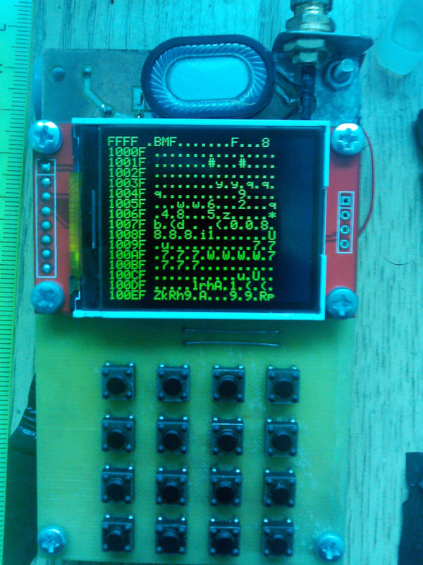
I’ll briefly cover a few main menu functions. The ATA command answers an incoming call; the ATH command rejects a call or ends it. The Data menu streamlines working with external memory and lets you view a live dump of any region, in ASCII or hex. You can also overwrite bytes at arbitrary addresses—including manually editing contact fields—though for that task the dedicated section is more convenient.
The Call menu is for quickly dialing numbers from the phonebook, while Tel Book lets you edit and add new contacts. The Power menu controls power-saving settings, and the sleep and sleep logo commands put the device into sleep mode (drawing about 6 mA and 9 mA, respectively).
There are a few other handy extras. The img menu acts as a gallery and gives you access to saved images, while sim800 talks directly to the radio module via standard AT commands. It might not be obvious, but this proved very handy during debugging.
Ideas and Future Development
I’ve really enjoyed working on my phone—rolling out features step by step, fixing bugs, and tackling challenges as they came up. And I’m definitely not stopping here. Here are a few ideas I haven’t shipped yet but have queued up for the near future: built-in games, data encryption, sending and receiving MMS, a notepad, and additional fields in contacts.
And that’s far from a complete list. Modern microcontrollers offer a wealth of useful interfaces and let you hook up all sorts of peripherals: external RAM chips, SD cards, high‑resolution displays, and even digital cameras. It’s easy to get carried away and try to build a full-fledged smartphone!