How Radio Receivers Went Mainstream
Progress never stops: over the last century, radio receivers kept getting cheaper while their performance steadily improved. In the 1920s, vacuum tubes made up most of the cost—think of Armstrong’s first superheterodyne receiver, which we’ve already mentioned when discussing the history of the superheterodyne.
When it first appeared, it seemed downright insane: it used eight vacuum tubes—an enormous number for that era. And it needed batteries that, all together, were about the size of a small suitcase.
By the 1930s, a receiver like that was very much a reality and even mass-produced. Indirectly heated tubes had also appeared, allowing the set to run off the mains. Prices were no longer sky-high. In the end, a receiver cost about what an iPhone does today, and you could finally put it on a table without worrying it would break the table.
The next phase of cost reduction and miniaturization progressed fairly slowly: vacuum tubes became cheaper and smaller, and circuit design kept improving. This continued up until the 1960s. The breakthrough came in the early 1950s, when the first mass-produced transistors appeared and the first mass-produced receiver, the Regency TR-1, was built around them.
By its specs it lagged behind the tube sets of the time and cost noticeably more, but you could finally slip it into a pocket. From there, transistors kept getting cheaper and better, and receivers shrank and became more power‑efficient along with them. Integrated circuits arrived, and by around the 1970s the number of transistors in a device no longer had a major impact on price. More and more of the size and cost was driven by the intermediate‑frequency (IF) filters and the tunable RF front‑end circuits.
Another leap came in the early 1980s, when Philips engineers managed to integrate the entire RF front end into a single chip. Thanks to some clever circuit design, they also eliminated all the tuned circuits except the local oscillator. The chip was named TDA7000, and the receiver prototype shown for promotional purposes looked rather unusual.

The design turned out remarkably successful, and soon there were the TDA7021 (PDF) with stereo support and the TDA7088 (PDF), which added automatic station search. The latter chip used a small digital block to handle the scanning. It was fairly primitive, but that approach stuck around for quite a while. These are the very receivers that were built into things like cigarette lighters in the early 2000s.
Russian engineers, though initially behind, absorbed the know‑how, which led to the release of the well-known K174XA34 (TDA7021), K174XA42 (TDA7000), and the rather quirky SXA058 hybrid module.

However, domestic manufacturers didn’t have the resources to develop a TDA7088 equivalent—or, more likely, it just stopped being a priority. In any case, all these chips are now considered obsolete and are no longer produced, except for TDA7088 clones—and even those probably won’t be around much longer.
We’ve entered the era of SDR/DSP receivers, where most signal processing is done mathematically on digitized data; we already discussed this when we built ZetaSDR. But in that setup, the digitized signal was processed on a PC. Can we do without a computer? Absolutely: back in 2001, Philips released the TEA5767 chip (PDF), a single‑chip digital receiver. It required minimal external components, offered digital control, and was marketed (PDF) as an easy‑to‑integrate option for gadgets like MP3 players and mobile phones. Its perks included crystal frequency stabilization and stereo decoding.

A bit later, a more advanced chip showed up: the RDA5807 (https://drive.google.com/file/d/0B3wGBsOmfWhVaTJQNkZ5YzJ0R28/view?resourcekey=0-k9dcSauW6X98kk4f4J_56Q). It did away with the last external LC tank in the surrounding circuitry. In fact, there’s practically no external circuitry left, while the receive band was noticeably expanded (64–108 MHz) and RDS support was added. Sensitivity improved, sound quality too, and—most impressively—this tiny chip can drive 32‑ohm headphones without an external amplifier. And all that for less than ten rubles! On top of that, the chip is backward-compatible with the RDA5807 and can even run without a host microcontroller. Still, it’s more fun with a controller.

But that’s not even the limit: you can also pack an LW/MW/SW receiver into the chip, as done in the KT0915 (PDF), AKC6951 (PDF) (this one can even pick up the first few TV channels), and the SI473x, which we’ll discuss next.
We’re going to build a modern radio receiver, comparable to commercial models like the PL-330 and the Eton Satellit—but ours will be as simple and efficient as possible.


Why the SI4734?
The SI4735 differs from the other chips mentioned in that it supports firmware patching, which unlocks additional features. For example, there’s a community patch that enables reception of SSB signals. What’s so special about that, you ask? Nothing particularly exotic—it’s just what amateur radio operators use on the HF bands, and it can be interesting to listen in sometimes. This is probably the simplest way to get an SSB-capable receiver.
Alright, we’ve sorted out the SI4735, so why does the title say SI4734? The thing is, all SI473x chips are pin-to-pin compatible and differ only in their feature sets. The lower-end models (SI4730, SI4731) support longwave and FM, while the higher-end ones (SI4732, SI4735) also support shortwave and RDS. The SI4734 supports shortwave but doesn’t do RDS. They also vary quite a bit in price: the SI4730 is about 100 rubles, the SI4734 around 150, and the SI4735 roughly 500 rubles. To be fair, just a year ago they were at least three times cheaper—but that’s a familiar problem these days.
The patch officially supports only the SI4735, which is what I planned to experiment with. But the unit I bought turned out to be dead, so I installed an SI4734-D60 I had in my spares. I also tried applying the patch to that chip and, to my surprise, it worked. So if you don’t need RDS, you can save some money.
Encouraged by that success, I tried tinkering with the SI4730-D60, especially since there were reports online that some of these chips can do shortwave (HF). Mine didn’t work, and the patch wouldn’t load on them either. It’s quite possible the patch will work on the SI4732, though, as Chinese vendors often include that chip in their receiver kits and advertise SSB support.
Circuit Design
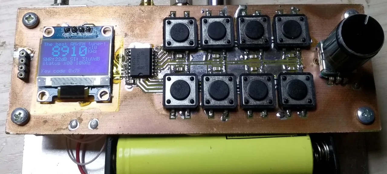
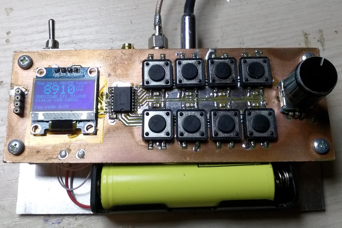
For our experiments, we’ll put together a relatively simple setup made of two modules: a control unit and a receiver module. The control unit will be built around an STM32F030, with a rotary encoder, an OLED display, and eight buttons. You can skip the buttons entirely, but they make operating the receiver much more convenient. The keypad will be handled by a PCF8574—an I2C I/O expander that’s very handy for this purpose. While adding an I/O expander slightly complicates the schematic, it simplifies PCB layout and button scanning. Powering everything from a LiPo battery is convenient, so we’ll add a charge controller and a DC/DC converter based on the RT9136 to power the MCU. Using a switching converter here makes sense to improve efficiency.

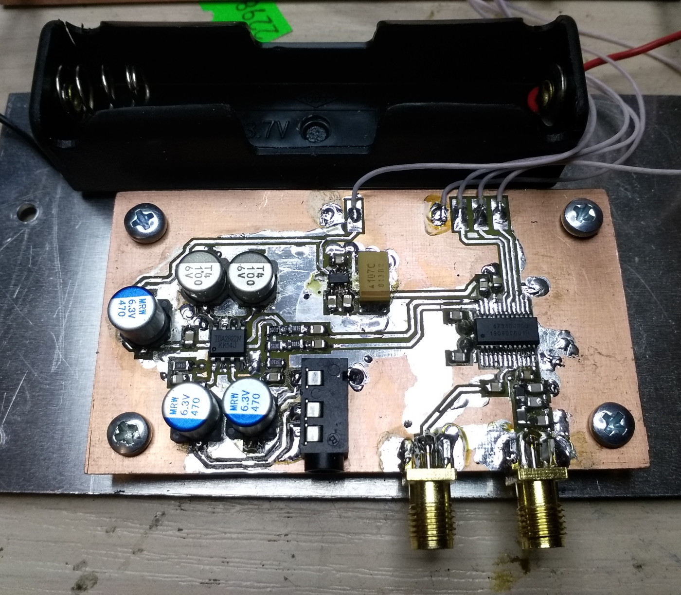
The SI4735’s output power isn’t enough to drive standard 32‑ohm headphones, so you need an audio amplifier—two, in fact, since it’s stereo. We used a TDA2822 amplifier IC (PDF) in the standard configuration. It’s not the best choice for two reasons: its gain is too high, and to my ear it’s a bit too noisy. An LM4863 (PDF) would be a better fit, but I didn’t have one on hand. That said, the TDA2822 does a decent job.
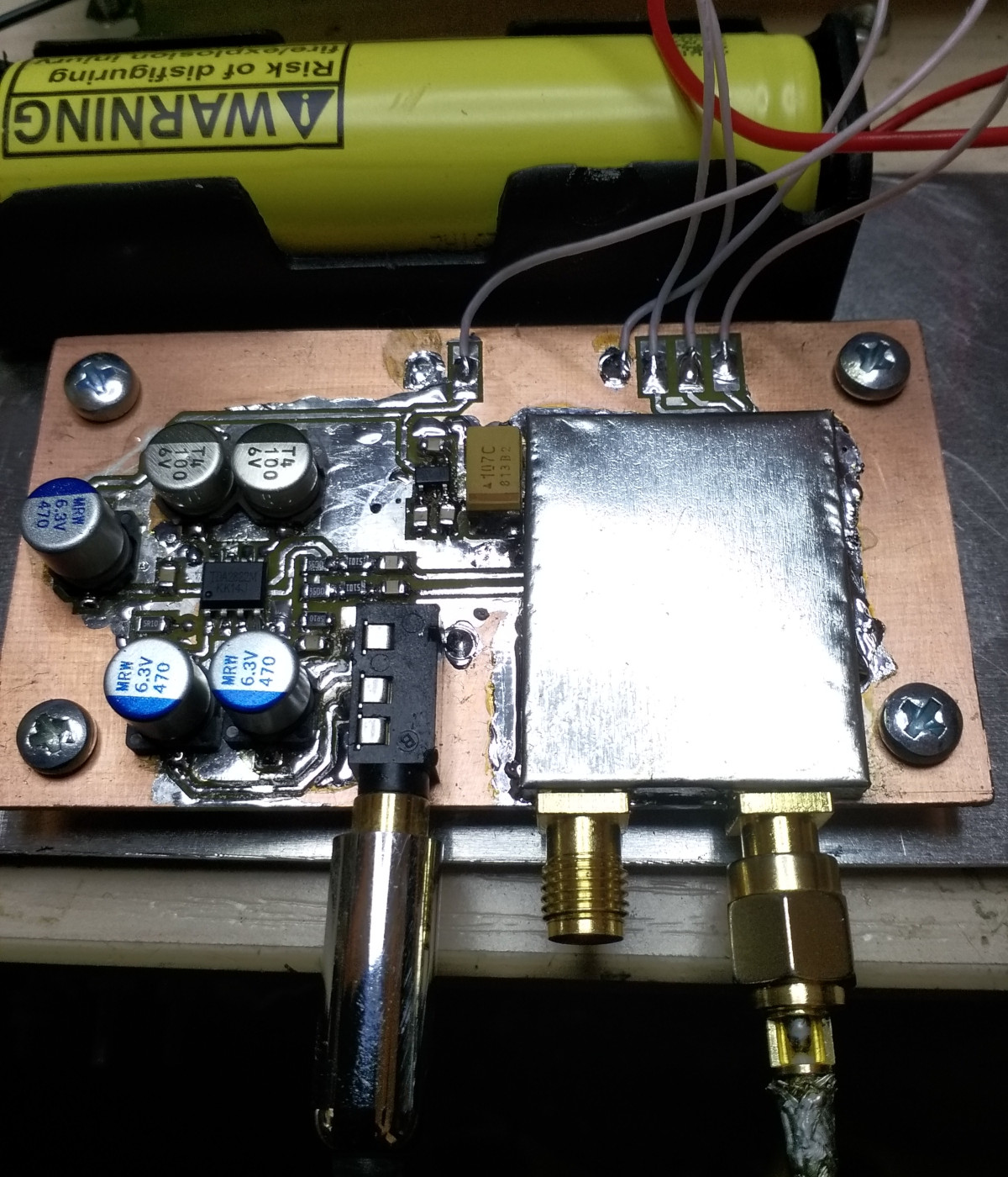
Commercial designs typically use an RF preamp (LNA) and a ferrite (magnetic) antenna, but we’ll keep it simpler: put a 5th‑order input filter with a defined cutoff frequency up front and use a full-size external antenna—after all, in an apartment a whip mostly picks up noise, FM, and maybe a couple of Chinese stations on a good day. As for the FM input, it works fine even without any input matching network. We’ll also place the SI4734 and its input circuitry inside a tinplate shield (the PCB is two-layer, with a solid copper pour on the second side), which is easy enough to do. Using an external full-size antenna will greatly reduce coupling from the digital section and eliminate the need for an RF preamp.
As for the digital part, there’s nothing special. The schematics, boards, and so on are on GitHub. Putting a constantly refreshing display and the keypad on the same bus as the SI4734 isn’t a great idea due to potential interference, but pausing the controller and turning off the display doesn’t make any audible difference. This suggests that, in the city, ambient RF noise has a much bigger impact on reception quality.
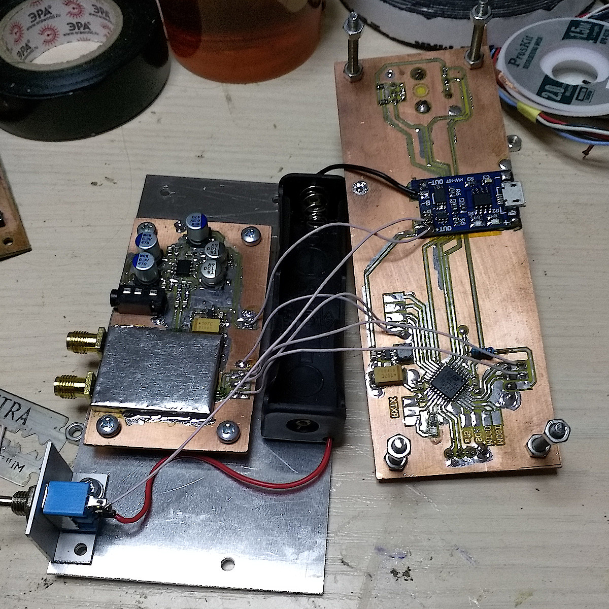
It’s put together in a fairly minimalist style; I’ve never been into building enclosures anyway. What I ended up with is something between a prototype and a finished device, but the receiver handled transport and field use without a hitch.
info
Anticipating the questions: the control unit can be built on either a Blue Pill or an Arduino; in the latter case, you can buy a preassembled board on AliExpress. That will run about 3,000 rubles. You can also spring for an enclosure if you want. But that’s not our style—we’re here to tinker with the SI4734!
Firmware
There are plenty of guides on building SI4735-based receivers, but most of them focus on the hardware and breadboard assembly, then flash one of the ready-made firmware builds. Here, we’ll figure out how to write that firmware ourselves almost from scratch, so everything that follows can be easily adapted to any other microcontroller—as long as it has enough memory to store the patch.
So what is the SI4734, and how do you work with it? The chip is controlled over I2C, and each transfer consists of the device address (with the read/write bit), a 1-byte command, and up to 7 argument bytes. Each command has its own number of arguments; however, the datasheet says you can use a fixed-length packet by sending 0x00 for any unused arguments. For our purposes we don’t need many commands, so we can just write a dedicated function for each. A command’s result is the response, which consists of a status byte and up to 7 bytes of data; here too you can standardize the length by always reading 8 bytes—any unused bytes will be 0x00.
There’s a catch: the command doesn’t complete instantly; there’s a delay during which the chip will return only zeros. So when we need the result, we poll the response at intervals until the first byte is 0x80, which signals the command has finished. After that, we can read the response bytes and/or send the next command.
To send and read I2C packets, we’ll use the familiar LibopenCM3 function i2c_transfer7(, where SI4734I2C is the I2C bus in use (I2C1) and SI4734ADR is the SI4734’s 7-bit address 0x11. The library handles the read/write bit for us. In short, working with the chip boils down to: initialization, selecting the operating mode, and tuning to the desired frequency. Everything described below is based on AN332 “Si47XX Programming Guide” and AN332SSB.
Initialization
First, you need to initialize the SI4734. You can do this in one of three modes: AM, FM, or SSB. The documentation recommends issuing a reset before initialization. That’s straightforward: briefly pull the SI4734’s RESET pin to ground. For the delay, a simple, imprecise function is fine—the exact timing isn’t critical here.
#define SI4734D60_RSTPORT GPIOA
#define SI4734D60_RSTPIN GPIO7
#define SI4734_RST_CLR() gpio_clear(SI4734D60_RSTPORT, SI4734D60_RSTPIN)
#define SI4734_RST_SET() gpio_set(SI4734D60_RSTPORT, SI4734D60_RSTPIN)
void delay(uint16_t ms){
  uint64_t temp;
  temp=ms<<10;
  while(temp--)__asm__("nop");
}
void si4734_reset(){
  SI4734_RST_CLR();
  delay(10);
  SI4734_RST_SET();
  delay(10);
}
Initialization uses the POWER_UP command, which takes two parameters. The first enables the clock and selects the operating mode, and the second configures the audio outputs. We use a crystal clock and analog outputs, so for FM we pass 0x10, 0x05, and for AM — 0x11, 0x05. After sending the command, we poll the chip until it returns 0x80. This usually takes one or two polls.
#define SI4734I2C I2C1
#define SI4734ADR 0x11
uint8_t si4734_fm_mode(){
  // ARG1 (1<<4)|0 AN322 p130
  // ARG2 00000101
  uint8_t cmd[3]={POWER_UP,0x10,0x05};
  uint8_t status, tray=0;
  i2c_transfer7(SI4734I2C,SI4734ADR,cmd,3,0,0);
  delay(1000);
  do{ i2c_transfer7(SI4734I2C,SI4734ADR,0,0,&status,1);
    tray++;
    if(tray==255) return 0xff;
    delay(50);
  }while(status!=0x80);
  return status;
}
uint8_t si4734_am_mode(){
  // ARG1 (1<<4)|1 AN322 p130
  // ARG2 00000101
  uint8_t cmd[3]={POWER_UP,0x11,0x05};
  uint8_t status, tray=0;
  i2c_transfer7(SI4734I2C,SI4734ADR,cmd,3,0,0);
  delay(1000);
  do{ i2c_transfer7(SI4734I2C,SI4734ADR,0,0,&status,1);
    tray++;
    if(tray==255) return 0xff;
    delay(50);
  }while(status!=0x80);
  return status;
}
In response to the POWER_UP command, the chip may return another 8 bytes that the datasheet recommends checking, but you can safely ignore them and not even read them. At this stage you can already verify that the IC is working: a good part will reply with 0x80 and start the crystal oscillator, which you can confirm with an oscilloscope. If the commands were sent correctly but the oscillator doesn’t start, the chip is likely defective.
What about SSB? Single-sideband is a bit trickier since it isn’t a standard feature. However, thanks to Vadim Afonkin, we have access to patches and documentation that enable SSB and NBFM reception. These are exactly what the SI4735 libraries on GitHub use, and we’ll use them too. In fact, we’ll pull the patch from the Arduino library, where it’s already packaged as a C array—just what we need.
The SI4734 has two commands for loading a patch into memory: 0x15 and 0x16. Each takes 7 bytes of arguments. Command 0x15 sets the target address in the SI4734’s memory where the patch will be written, and 0x16 uploads the patch itself, 7 bytes per call. As you’d expect, after each command you must wait for the 0x80 response.
The patch is an array containing those commands and their arguments, so your job is to read the array in 8-byte chunks, send them to the chip, and wait for it to process each chunk. Given the patch’s size, the whole upload takes about a second.
Overall, the flow is similar to the AM initialization sequence described above, except you set the “patch receive” bit in the first argument: RST POWER_UP 0x31, 0x05. Then you stream the patch.
const uint8_t ssb_patch_content[] = {0x15, 0x00, 0x03, 0x74, 0x0B, 0xD4, 0x84, 0x60, ... 0x15, 0x00, 0x00, 0x00, 0x00, 0x00, 0xA9, 0x02};// 0x451 linesuint8_t si4734_ssb_patch_mode(uint8_t *patch){ // ARG1 (1<<5)|(1<<4)|1 AN322SSB p7 // ARG2 00000101 uint8_t cmd[3]={POWER_UP,0x31,0x05}; uint8_t status, tray=0; uint16_t count,iterate=0; i2c_transfer7(SI4734I2C,SI4734ADR,cmd,3,0,0); delay(1000); do{ i2c_transfer7(SI4734I2C,SI4734ADR,0,0,&status,1); tray++; if(tray==255) return 0xff; delay(50); }while(status!=0x80); if(status!=0x80) return 0x1; count=0x451; while(count--){ tray=0; i2c_transfer7(SI4734I2C,SI4734ADR,patch+iterate,8,0,0); iterate+=8; delay(2); do{ i2c_transfer7(SI4734I2C,SI4734ADR,0,0,&status,1); tray++; if(tray==255) return 0x02; delay(1); }while(status!=0x80); } return status;}si4734_ssb_patch_mode(ssb_patch_content);
info
If you have one of these receiver implementations, you can figure out which patch it uses by sniffing the I2C bus and catching messages that start with 0x11, and 0x11, . A logic analyzer makes this straightforward.
Immediately after flashing the patch, the speakers emit a distinctive “grunt.” Bricking the chip with a bad patch appears to be impossible: on reset, the factory firmware is restored, and an invalid patch simply won’t run. At least, the SI4730 units I tested operated normally after a reset.
Operating Mode Configuration
Once initialization completes, the factory-programmed defaults take effect. If you just want to get it up and running quickly, you can skip this step. The SI4734 has dozens of tunable parameters, many of them mode-specific, and the chip will work just fine with the stock settings. That said, it’s worth tweaking a few of them—especially for SSB.
Let’s start with the basics: FM. The SI4734 defaults to the US pre-emphasis setting, which should be switched to the European standard. To do that, use the SET_PROPERTY 0x12 command; it takes five arguments. The first is 0x00, followed by two bytes for the property ID (most significant byte and least significant byte), and then two bytes for the value to write (most significant byte and least significant byte).
uint8_t si4734_set_prop(uint16_t prop, uint16_t val){
  uint8_t cmd[6]={SET_PROPERTY,0,(prop>>8),
                  (prop&0xff),(val>>8),(val&0xff)};
  uint8_t status;
  i2c_transfer7(SI4734I2C,SI4734ADR,cmd,6,0,0);
  delay(100);
  i2c_transfer7(SI4734I2C,SI4734ADR,0,0,&status,1);
  return status;
}
Here, instead of continuously polling the chip for a response, we use a fixed delay, which you’ll need to calibrate. Now, using this function, we’ll modify the parameter we care about and also set the desired volume.
#define FM_DEEMPHASIS 0x1100
#define RX_VOLUME    0x4000
si4734_set_prop(FM_DEEMPHASIS,0x0001);// 01 = 50 µs. Used in Europe, Australia, Japan
si4734_set_prop(RX_VOLUME, vol);
AM has a few more parameters. Let’s widen the bandwidth to 6 kHz—without that, broadcast stations sound unnaturally muffled, and they play music too. We’ll also enable 100 Hz mains-hum suppression. I’m not sure how effective it is, but it doesn’t hurt. Both of these are controlled by the command AM_CHANNEL_FILTER . You could stop there, but to pull in weaker stations it’s worth disabling the squelch, adding gain in the AF path, and setting the volume. In general, the setup looks like this:
#define AM_CHANNEL_FILTER 0x3102
#define AM_SOFT_MUTE_MAX_ATTENUATION 0x3302
#define AM_AUTOMATIC_VOLUME_CONTROL_MAX_GAIN 0x3103
si4734_set_prop(AM_CHANNEL_FILTER, 0x0100);
si4734_set_prop(AM_SOFT_MUTE_MAX_ATTENUATION, 0);// soft mute off
si4734_set_prop(AM_AUTOMATIC_VOLUME_CONTROL_MAX_GAIN, 0x5000); // 60 dB
si4734_set_prop(RX_VOLUME, vol);
And finally, SSB. This one needs a bit more tweaking: set the mode with SSB_MODE and set the bandwidth to 3 kHz (targeting voice signals). Disable AFC and enable automatic volume control (AGC). Then add gain in the audio path and turn off the squelch. The parameter codes are the same as for AM. Set the volume in the same way.
#define SSB_MODE 0x0101si4734_set_prop(SSB_MODE,((1<<15)|(1<<12)|(1<<4)|2));// ssb man page 24si4734_set_prop(AM_SOFT_MUTE_MAX_ATTENUATION, 0);// soft mute offsi4734_set_prop(AM_AUTOMATIC_VOLUME_CONTROL_MAX_GAIN, 0x7000); // 84 dBsi4734_set_prop(RX_VOLUME, vol);That’s it for the preliminary setup—pretty painless, really. All that’s left is to set the frequency.
Frequency Tuning
Tuning the frequency differs slightly across modes: it’s easiest in FM and AM, and a bit trickier in SSB. Let’s start with FM. To tune to a specific frequency, use the FM_TUNE_FREQ 0x20 command, which takes four parameters. The first controls tuning speed at the expense of accuracy; set it to 0x00. In FM this isn’t particularly critical. The next two are the high and low bytes of the frequency in tens of kilohertz, and the last one is the input capacitance trim. It’s recommended to set that to 0x00 (auto-tune) when receiving on a short whip antenna, which we’ll do. Same as before: send the command with parameters and wait for the 0x80 response.
uint8_t si4734_fm_set_freq(uint16_t freq_10khz){
  uint8_t fast,freq_h,freq_l,status,tray=0;
  fast=0;
  freq_h=freq_10khz>>8;
  freq_l=freq_10khz&0xff;
  uint8_t cmd[6]={FM_TUNE_FREQ,fast,freq_h,freq_l,0,0};
  i2c_transfer7(SI4734I2C,SI4734ADR,cmd,6,0,0);
  delay(20);
  //do{
  //  status=si4734_get_int_status();
  //  delay(50);
  //} while(!status || status&1);
  do{
    i2c_transfer7(SI4734I2C,SI4734ADR,0,0,&status,1);
    tray++;
    if(tray==255) return 0xff;
    delay(20);
  }while(status!=0x80);
  return status;
}
The usable frequency range is 6,300–10,900 kHz, slightly wider than the datasheet; beyond that, the chip returns an error. With AM it’s almost the same, except the command code is different — AM_TUNE_FREQ — and there are five parameters. The first enables fast tuning at the expense of accuracy (0x00/0x01 for off/on, respectively). Next come two bytes of the frequency in kilohertz (high then low), followed by two bytes for the input capacitance setting (0x00 for auto-calibration).
Auto‑tuning works well on long and medium waves when a ferrite loop antenna is connected to the AMI input, as it lets you tune the antenna to resonance. But since we’re using an external full‑size antenna and there’s also an LPF at the input, we’ll disable this tuning by setting the two bytes to their minimum, 0x00 . It would be interesting to put a resonant network at the input and tweak these parameters, but that would complicate the design and is unlikely to deliver a significant benefit.
As for the first parameter, it’s debatable—should you enable accelerated tuning or not? On the one hand, AM requires more precise tuning; on the other, these chips have an annoying quirk often called “chuffing”—those chuff-chuff noises when the frequency steps. It’s pretty irritating, especially at first. Enabling accelerated tuning reduces this effect a bit, and the loss of precision is offset by the automatic frequency control (AFC), which is on by default. So try both and pick what you like better. Here’s the resulting function.
uint8_t si4734_am_set_freq(uint16_t freq_khz){
  uint8_t fast,freq_h,freq_l,status,tray=0;
  fast=1;
  freq_h=freq_khz>>8;
  freq_l=freq_khz&0xff;
  uint8_t cmd[6]={AM_TUNE_FREQ,fast,freq_h,freq_l,0,1};
  i2c_transfer7(SI4734I2C,SI4734ADR,cmd,6,0,0);
  delay(20);
  do{
    i2c_transfer7(SI4734I2C,SI4734ADR,0,0,&status,1);
    tray++;
    if(tray==255) return 0xff;
    delay(20);
  }while(status!=0x80);
  return status;
}
Now for SSB. The command is the same as for AM, with the same number of parameters; the only difference is that the first parameter selects which sideband we’re listening to—LSB (0b01000000) or USB (0b10000000). There’s a convention that below 10 MHz you use LSB, and above that you use USB. There are exceptions, but we’ll ignore them here and derive the first argument from the frequency. The other four parameters are the same as in AM. So we end up with a function like this.
uint8_t si4734_ssb_set_freq(uint16_t freq_khz){
  uint8_t mode,freq_h,freq_l,status,tray=0;
  if(freq_khz>10000)mode=0b10000000;else mode=0b01000000;
  freq_h=freq_khz>>8;
  freq_l=freq_khz&0xff;
  uint8_t cmd[6]={AM_TUNE_FREQ,mode,freq_h,freq_l,0,1};
  i2c_transfer7(SI4734I2C,SI4734ADR,cmd,6,0,0);
  delay(20);
  do{
    i2c_transfer7(SI4734I2C,SI4734ADR,0,0,&status,1);
    tray++;
    if(tray==255) return 0xff;
    delay(20);
  }while(status!=0x80);
  return status;
}
A seasoned reader will notice that a 1 kHz tuning step for SSB is inadequate, because the amount of detuning sets the audio pitch, and being off by just a few hundred hertz can make speech unintelligible. Our crystal oscillator isn’t perfect either, and the same issue can occur on the transmitting side.
Therefore, you need to provide a way to fine-tune the frequency. For that there’s the SSB_BFO parameter, which accepts values from -16383 to +16383 and specifies a frequency offset in hertz relative to the value set by AM_TUNE_FREQ. The datasheet claims the actual tuned frequency is AM_TUNE_FREQ (, but my experiments show that on the SI4734 you have to subtract the BFO from the base frequency, i.e., AM_TUNE_FREQ (. Whether that’s specific to the SI4734 or just a datasheet error isn’t all that important. In the end, we set the BFO with si4734_set_prop(, where bfo is the desired offset in hertz (a signed 16-bit integer).
Putting It All Together
We now have all the essential functions to start the SI4734 in any of its three modes. Let’s wrap them into a single function that takes the desired mode as an argument. We’ll also add a si4734_powerdown( function, which will let us not only start from a powered-off state but also switch between already configured modes. As the name suggests, this command programmatically powers down the SI4734.
#define AM_MODE 0#define FM_MODE 1#define SSB_MODE 2uint16_t encoder=15200;uint16_t pwm1=750;uint16_t coef=5;int16_t bfo=0;int16_t vol=0x1a;uint8_t si4734_powerdown(){ uint8_t cmd=POWER_DOWN,status; i2c_transfer7(SI4734I2C,SI4734ADR,&cmd,1,0,0); delay(200); i2c_transfer7(SI4734I2C,SI4734ADR,0,0,&status,1); return status;}void reciver_set_mode(uint8_t rec_mod){ static uint16_t amfreq=15200,fmfreq=8910; // Remember the previous value si4734_powerdown(); // frequencies if(reciver_mode==FM_MODE)fmfreq=encoder; else amfreq=encoder; if(rec_mod==AM_MODE){ reciver_mode=AM_MODE; si4734_am_mode(); si4734_set_prop(AM_CHANNEL_FILTER, 0x0100); si4734_set_prop(AM_SOFT_MUTE_MAX_ATTENUATION, 0); // soft mute off si4734_set_prop(AM_AUTOMATIC_VOLUME_CONTROL_MAX_GAIN, 0x5000); // 60 dB si4734_set_prop(RX_VOLUME, vol); encoder=amfreq-bfo/1000; // BFO correction si4734_am_set_freq(encoder); coef=1; encoder_mode=0; }else if(rec_mod==FM_MODE){ reciver_mode=FM_MODE; si4734_fm_mode(); si4734_set_prop(FM_DEEMPHASIS,0x0001); // 01 = 50 µs. Used in Europe, Australia, Japan si4734_set_prop(RX_VOLUME, vol); MIN_LIMIT=6000; MAX_LIMIT=11100; coef=10; encoder=fmfreq; si4734_fm_set_freq(encoder); encoder_mode=0; }else{ reciver_mode=SSB_MODE; si4734_ssb_patch_mode(ssb_patch_content); si4734_set_prop(0x0101,((1<<15)|(1<<12)|(1<<4)|2)); // ssb man page 24 si4734_set_prop(AM_SOFT_MUTE_MAX_ATTENUATION, 0); // soft mute off si4734_set_prop(AM_AUTOMATIC_VOLUME_CONTROL_MAX_GAIN, 0x7000); // 84 dB si4734_set_prop(RX_VOLUME, vol); encoder=amfreq; si4734_ssb_set_freq(encoder); coef=1; encoder_mode=0; }}So, to start the chip, for example in FM mode at frequency freq, you only need to call three functions:
si4734_reset();
for(uint32_t i=0;i<0x5ff;i++)__asm__("nop"); // Delay required by the datasheet
reciver_set_mode(FM_MODE);
si4734_fm_set_freq(freq);
To switch to another mode, just call the last two functions, since a reset is recommended only at power-up. To retune the frequency, the last function alone is enough. Our receiver is already operational; now we just need to add some UI polish and extra features.
Adding polish and features
For the display, I used a custom library I’d written for previous projects. It can render formatted strings of a specified size at given screen coordinates, and that text-only UI is more than sufficient. From the configured tuner chip we can read several signal parameters—current tuned frequency, signal strength, signal-to-noise ratio, and more. Since we set the frequency directly, there’s no real need to query the chip for it, but it is useful to see the strength and noise level. In SSB mode there’s also the BFO, which we should display as well. In that mode we’ll also apply a correction to the displayed frequency to account for the BFO. So, the display function will look like this.
void show_freq(uint16_t freq, int16_t offset){ uint16_t offset_hz; uint16_t freq_khz; if(reciver_mode==FM_MODE)o_printf_at(18*5,1,1,0,"x10"); else o_printf_at(18*5,1,1,0," "); // f=f-bfo if(reciver_mode==SSB_MODE){ offset_hz=(1000-offset%1000)%1000; freq_khz=freq-offset/1000; if(offset%1000>0)freq_khz--; o_printf_at(18*5,3,1,0,"%03d",offset_hz); o_printf_at(0,1,3,0,"%5d",freq_khz); }else{ o_printf_at(18*5,3,1,0," "); o_printf_at(0,1,3,0,"%5d",freq); } o_printf_at(18*5,2,1,0,"KHz");}void show_reciver_status(uint8_t snr, uint8_t rssi, uint8_t status){ uint8_t n=1; o_printf_at(1,4,1,0,"SNR:%2ddB SI: %2duVdB",snr,rssi); // coef — global variable // n — step correction factor if(reciver_mode==FM_MODE)n=10; o_printf_at(1,5,1,0,"status x%x %dKHz ",status,coef*n);}void show_reciver_full_status(uint16_t freq, int16_t offset, uint8_t snr, uint8_t rssi, uint8_t status){ show_freq(freq, offset); show_reciver_status(snr,rssi,status);}Here, reciver_mode is a global variable holding the current mode code, which slightly changes the UI; freq is the current tuned frequency; offset is the frequency offset in SSB mode; snr is the signal-to-noise ratio in decibels; rssi is the signal strength in dBµV; status is the status byte returned by the set-frequency command. The latter helps with debugging. The global variable coef controls the encoder’s tuning step: for AM/SSB it’s in kilohertz, and for FM it’s in tens of kilohertz. The integer arithmetic compensates for the frequency offset. And it all looks like this.


We can obtain the rssi and snr values using the AM_RSQ_STATUS or FM_RSQ_STATUS commands, and the commands for SSB and AM are identical:
uint8_t si4734_am_signal_status(uint8_t *resp1,uint8_t *resp2,uint8_t *rssi,uint8_t *snr){ uint8_t cmd[3]={AM_RSQ_STATUS,0x1}; uint8_t tray=0; uint8_t answer[6]; i2c_transfer7(SI4734I2C,SI4734ADR,cmd,2,0,0); delay(50); answer[0]=0; while(answer[0]==0){ i2c_transfer7(SI4734I2C,SI4734ADR,0,0,answer,6); tray++; if(tray==255) return 0xff; delay(50); } *resp1=answer[1]; *resp2=answer[2]; *rssi=answer[4]; *snr=answer[5]; return answer[0];}uint8_t si4734_fm_signal_status(uint8_t *rssi,uint8_t *snr,int8_t *freq_of){ uint8_t cmd[3]={FM_RSQ_STATUS,0x1}; uint8_t tray=0; uint8_t answer[8]; i2c_transfer7(SI4734I2C,SI4734ADR,cmd,2,0,0); delay(50); answer[0]=0; while(answer[0]==0){ i2c_transfer7(SI4734I2C,SI4734ADR,0,0,answer,8); tray++; if(tray==255) return 0xff; delay(50); } *rssi=answer[4]; *snr=answer[5]; *freq_of=answer[7]; return answer[0];}uint8_t get_recivier_signal_status(uint8_t *snr,uint8_t *rssi,uint8_t *freq_of){ uint8_t status,resp1,resp2; switch(reciver_mode){ case AM_MODE: status=si4734_am_signal_status(&resp1,&resp2,rssi,snr); break; case FM_MODE: status=si4734_fm_signal_status(rssi,snr,freq_of); break; case SSB_MODE: status=si4734_am_signal_status(&resp1,&resp2,rssi,snr); break; } return status;}Let’s get back to the tuning step. We can choose the step size ourselves: since we can set the frequency with 1 kHz resolution in AM/SSB and 10 kHz in FM, practical step sizes are 1, 5, and 10 kHz, and for FM it’s convenient to multiply those by 10.
With SSB, there’s a small hack that almost eliminates the “chuffing” problem. We use the fine frequency offset, which doesn’t produce clicks. Unfortunately, it’s limited to ±16 kHz, but if we track the BFO and, upon reaching ±16,000, reset the BFO and then nudge the main tuning, we get effectively continuous tuning with roughly 10 Hz resolution. The datasheet claims 8 Hz resolution for the offset; not a big deal—at this price, the main thing is that it doesn’t drift. In practice, a 100 Hz step is convenient: it’s still accurate enough to zero in without wearing out your wrist on the knob. And you can still set the main tuning step to anything you like. The hack looks like this:
if(old_bfo!=bfo && reciver_mode==2){ si4734_set_prop(SSB_BFO, bfo); o_printf_at(1,6,1,0,"BFO: %d ",-bfo); if(bfo>16000||bfo<-16000){ encoder=encoder-bfo/1000; bfo=bfo%1000; } old_bfo=bfo;}if(old_encoder!=encoder){ old_encoder=encoder; if(reciver_mode==1) status=si4734_fm_set_freq(encoder); else if(reciver_mode==2) status=si4734_ssb_set_freq(encoder); else status=si4734_am_set_freq(encoder);}One last thing worth mentioning is the station auto-scan. It’s a really handy feature when you don’t feel like turning the knob. I only implemented it for AM, since on FM the stations here are lined up about every 400 kHz—so what’s there to search for?
You can scan in either direction—up or down—and you have to set the tuning step. Only fixed steps of 1, 5, or 10 kHz are supported. A 1 kHz step is more thorough but slower; 5 kHz is faster but may skip over signals. I went with 5 kHz.
Next, choose the search criterion: RSSI or SNR. Given how noisy my band is, searching by signal strength is pointless, so I use SNR and set the threshold to the minimum, 1 dB. In any case, if a station can’t muster at least 1 dB SNR, you won’t really be able to listen to it.
Next, set the search boundaries. The current frequency must lie between the upper and lower bounds, otherwise the seek won’t work. In the examples I’ve seen, all HF sub-bands were stored in memory and the search was confined to those. I find that inconvenient: first, broadcast stations can show up outside the defined sub-bands (some Chinese stations don’t strictly follow the band plan), and second, scanning an entire sub-band can take quite a while. So each time I invoke a search, I’ll set the bounds to ±200 kHz from the current frequency. Finally, for a failed search, stop at the corresponding boundary.
After the scan completes, you need to read the frequency the chip locked onto and update the controller’s frequency value so it’s displayed correctly. This time, we’ll wait for the chip to return 0x81, which signals the end of the search. Strictly speaking, 0x81 is 0x80|0x01, where 0x80 indicates the chip is ready to accept further commands, and 0x01 indicates that tuning has finished. In the frequency retune commands discussed above, if you keep polling the chip’s status after receiving 0x80, the chip will eventually return 0x81. In code, it looks like this.
...// This part is tied to the buttonif(reciver_mode==AM_MODE){ si4734_am_seek(encoder,1); // Seek up si4734_get_freq_v2(&encoder);}...// This part is tied to the buttonif(reciver_mode==AM_MODE){ si4734_am_seek(encoder,0); // Seek down si4734_get_freq_v2(&encoder);}...void si4734_am_seek(uint16_t freq, uint8_t up){ uint8_t cmd[6]={AM_SEEK_START,(1<<3),0,0,0,1}; // AN332 p138 uint16_t top,bottom; // To keep the receiver from hanging too long during search, limit the range to 400 kHz top=freq+200; if(top>30000)top=30000; if(freq<400) bottom=200;else bottom=freq-200; si4734_set_prop(AM_SEEK_BAND_TOP,top); si4734_set_prop(AM_SEEK_BAND_BOTTOM,bottom); si4734_set_prop(AM_SEEK_FREQ_SPACING,5); // Seek step si4734_set_prop(AM_SEEK_SNR_THRESHOLD,1); // Threshold 1 dB // uint16_t freq; // uint8_t rssi,snr; if(!up) cmd[1]&=~(1<<3); i2c_transfer7(SI4734I2C,SI4734ADR,cmd,6,0,0); // delay(500); while (si4734_get_int_status()!=0x81)delay(100);}uint8_t si4734_get_freq_v2(uint16_t *freq){ // Returns frequency only uint8_t cmd[2]={AM_TUNE_STATUS,0x0}; uint8_t tray=0; uint8_t answer[8]; i2c_transfer7(SI4734I2C,SI4734ADR,cmd,2,0,0); delay(50); answer[0]=0; while(answer[0]==0){ // If all is OK, the response will be 0x81 i2c_transfer7(SI4734I2C,SI4734ADR,0,0,answer,8); tray++; if(tray==255) return 0xff; delay(50); } *freq=((answer[2]<<8)|answer[3]); return answer[0];}Interestingly, if you poll the Si473x chip for the current frequency during a scan, you can watch it stepping through the configured range until it finds a station or hits the scan limit. Further implementation details are on GitHub: full source code, schematics, PCB layouts, and useful datasheets.
Impressions
My impressions of the SI4734 are positive overall, and I really have just one complaint—the chuffing while tuning AM/SSB. A dual-conversion analog receiver is much nicer to tune; however, considering the simplicity of the design and the very affordable price of this Si chip, that shortcoming is easy to forgive.
FM performance is excellent—no complaints there. Sensitivity is solid as well: in SSB mode it clearly picks up a signal generator at around 0.5 µV. So if you use it away from noise sources—out of town or at least in a park—there’s always something to listen to on the AM/SSB bands. In the city it’s not bad either, though there the results depend entirely on the antenna.
Ironically, this receiver performs better on the CB band (27 MHz AM) than the RTL-SDR v3. That’s likely due to the RTL-SDR v3’s internal noise; otherwise, the latter is superior overall. But if you want to listen to the airwaves outdoors and don’t feel like lugging a laptop, the SI4734 is just the ticket.