There’s no single “right” way to build digital-to-analog converters (DACs) because there’s no unifying paradigm. There are only collections of approaches, methods, schools, and philosophies — and, in the end, they’re all just sets of conventions.
I’ll share my personal experience, but only cover the key points. I won’t touch on power supply design, amplifiers, acoustics, and so on—that’s a matter of personal preference.
If you decide to replicate the experiments, make sure to heed the warning.
warning
The author and editors make no warranties and accept no liability for any harm caused while attempting to reproduce the techniques described in this article. Anything you do, you do at your own risk. Although all schematics were tested in practice, they are intentionally simplified and are provided to illustrate the operating principle, not as finished products.
PCM (Pulse‑Code Modulation) DAC
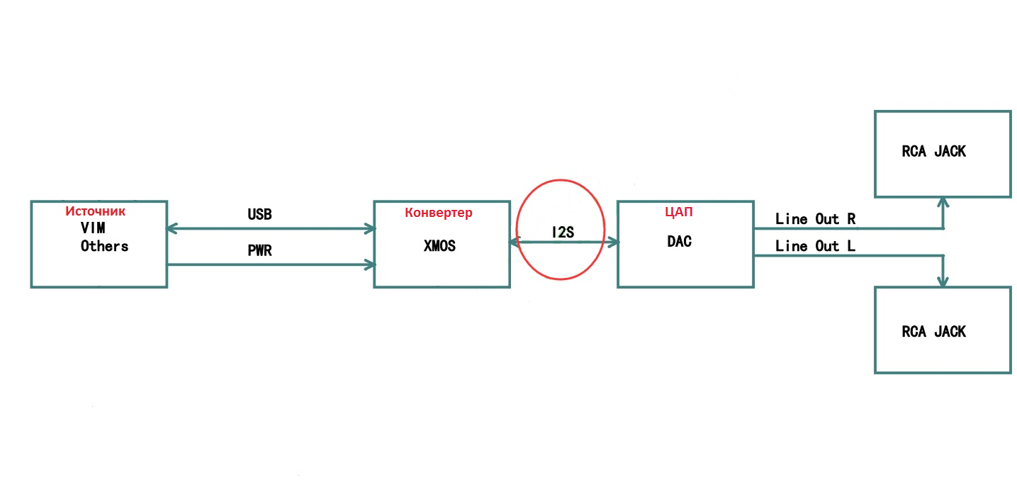
Typically, the audio signal chain can be divided into three parts:
- Source
- I2S converter
- I2S DAC
Audio Source
The source can be a computer, tablet, phone, or a single-board computer like a Raspberry Pi. In some cases, the source and the converter are combined in one device—for example, media players with an I2S output or single-board computers.
I2S Converter
I2S converters can connect to the source via various interfaces: USB, S/PDIF, or LAN. There are Bluetooth variants, but we’re not interested in them because you can’t achieve high-quality audio in such a setup. Bluetooth’s data rate is too low—Hi-Res (192 kHz/24-bit, DSD) is off the table. Even when playing MP3 (44.1 kHz/16-bit), the digital stream passes through multiple digital filters and undergoes additional bandwidth limiting of the audio signal.
By the way, the same goes for Bluetooth headphones. It’s even worse there: because of the limited space, it’s hard to fit a full-fledged DAC (digital-to-analog converter) and its power supply, so manufacturers typically use stripped-down versions.
www
For a deep dive into Bluetooth audio, read the article “Audio over Bluetooth: an in‑depth look at profiles, codecs, and devices”.
USB
The most common type of I2S converter is the USB-to-I2S converter.
It’s simple: connect it to the source device’s USB port, install the driver, and during playback the I2S output carries a PCM or DSD data stream. The operating system recognizes the converter as an audio device or sound card. There are plenty of USB-to-I2S converters on the market—searching for “usb to i2s” on AliExpress or eBay will turn up dozens of options.
S/PDIF
Many commercial, proprietary DACs connect via the S/PDIF interface.
Not long ago, S/PDIF was a popular interface and showed up on almost every sound card, including the cheapest onboard solutions on PC motherboards. What many don’t realize is that S/PDIF is almost always just an intermediate link, used primarily as a transport. On either the source side or the DAC side, S/PDIF is usually tied into I2S. In other words, the signal isn’t sent directly end‑to‑end: it’s first converted from I2S to S/PDIF, and then converted back.
I won’t cite exact figures, but it’s generally accepted that there are losses during conversion and transmission. S/PDIF also has other drawbacks—transfer rate and cost. The cheapest DIY USB-to-S/PDIF devices run about 4,000 rubles, and they max out at PCM 192/24 or DSD64 via DoP.
So, there’s little reason to use S/PDIF if other options are available.
LAN
Now let’s look at connecting an I2S converter over a LAN (local network). This is done using specialized software players: Squeezelite, HQPlayer, Roon, and others. These are installed on the main computer, which acts as the transmitter (source). During playback, the digital stream is unpacked, decoded, and, if needed, processed. The digital audio stream is then sent to the receiver—most often a single-board computer—over a specific network protocol. The microcomputer either converts the incoming stream to I2S itself or passes it to a USB-connected converter. There are both DIY solutions based on boards like the BeagleBone Black or Raspberry Pi, and production units from various manufacturers.
It’s common to find devices that combine a source and a converter, a converter and a DAC, or all three in a single unit.
I2S DAC
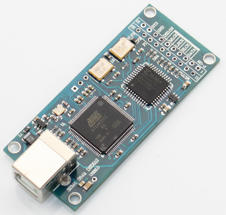
There’s no shortage of DACs with an I2S input. We won’t be covering fully assembled, mass‑market units; we’re more interested in DIY builds. The easiest and cheapest way to try out a given DAC is to buy a prebuilt DAC board. You can look for one without a power supply or preamp stage if you want to add those yourself. For a first run, go with something simple and inexpensive—like a PCM5102A‑based board as shown in the photo.

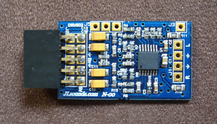
In my setup, I’ll be using an Amanero converter from Amanero Technologies.
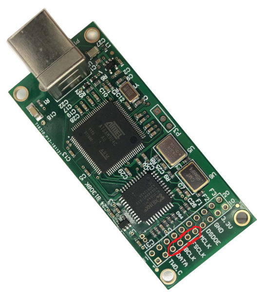
You can power the PCM5102A directly from the converter: connect VIN to the 3.3 V pin, GND to the converter’s ground, LRCK (LCK) to the converter’s FSCLK, DIN to DATA, and BCK to BCLK. The SCK/MCLK pins on the PCM5102A don’t have to be connected—it can operate without an external master clock. However, if you want better accuracy and you have the option, it’s preferable to connect MCLK. You can hook up this DAC to a Raspberry Pi in the same way.
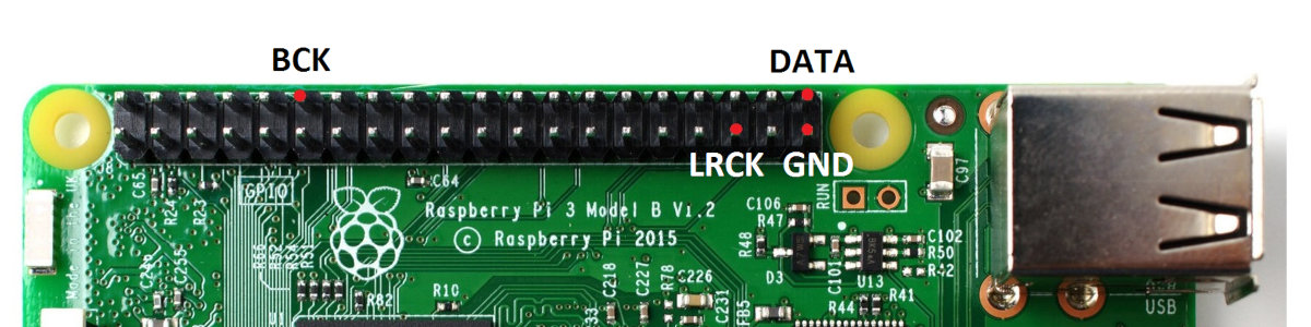
As you can see, it’s straightforward and doesn’t require any special expertise. You can hook up other DACs to I2S the same way. For USB playback, pretty much any player will work. On a Raspberry Pi, beginners can try Volumio, while more advanced listeners might prefer a build with Album Player.
For beginners, this should be enough for a first run. If you’re up for a challenge, read on—the difficulty will ramp up.
DSD DAC
We’ll examine practical ways to transmit and play back DSD.
In DIY builds, the DSD bitstream typically travels from the source to the digital-to-analog converter (DAC) through an I2S converter. Not all converters support DSD, so before buying, make sure the spec sheet explicitly lists DSD support. The most affordable USB-to-I2S options with DSD support are Amanero-based boards (and their clones) and converters built on XMOS processors.
Note that not all players support DSD playback, and not all drivers can pass native DSD, even if the player can. You can work around driver limitations by using DoP (DSD over PCM); accordingly, the player also needs to be able to convert/wrap DSD into DoP.
With Amanero and XMOS, the DSD stream is delivered to the DAC over the same I2S pins: DATA carries the right-channel data, LRCK carries the left, and BCLK provides the bit clock.
There are several ways to play back a DSD stream; three are worth highlighting:
- proprietary DACs
- using a low-pass filter (LPF)
- DIY DACs
Proprietary DAC
Most commercial DACs that support DSD playback accept both PCM and DSD over the same I2S interface. In that case, it’s enough to wire the converter and DAC pins as described above, and switching between PCM and DSD will work automatically. Some devices have dedicated DSD inputs, but those are meant for separate connections; in most cases you don’t need to use them.
Playback through a Low-Pass Filter
This method wins you over with its simplicity and, frankly, its surprisingly good sound. As the name suggests, it plays DSD straight through a low-pass filter, without any digital-to-analog converter in the chain. When I first heard about it, I was skeptical, but it turned out to sound better than any DAC I’d listened to before. I’m not trying to persuade anyone, but I doubt I’ll go back to proprietary DACs.
The only downside is that there’s far less content available in DSD than for Audio CD. However, PCM-to-DSD conversion solves that—it can be done ahead of time, before listening, or on the fly. You can do this on a PC or on iOS and Android devices, with an I2S converter acting as the transport.
How it works
The DSD format uses pulse‑density modulation. On the I2S output, consecutive positive pulses (logic 1s) merge into a single, longer pulse, which makes the voltage rise. When there are no positive pulses, the voltage falls.
The ones and zeros come as a serial bitstream, so if you feed the output of a DSD channel into a low-pass filter and remove the DC offset, you can recover an analog waveform that can be sent straight to an amplifier. That’s essentially how 1‑bit sigma‑delta DACs converted a digital bitstream into an analog signal.
Filter Selection
A simple RC or RL network can serve as a low-pass filter, and a regular capacitor is sufficient to remove the DC component of a signal.
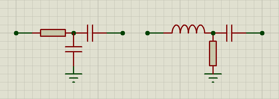
These filters are easy to calculate. For an RC (resistor–capacitor) filter, use fc = 1/2πRC; for an RL (resistor–inductor) filter, use fc = R/2πL, where fc is the cutoff frequency. A cutoff in the 25–50 kHz range is a good choice.
The capacitor value (in the schematic on the right) used to remove the DC component is chosen using the standard RC high-pass filter calculation.
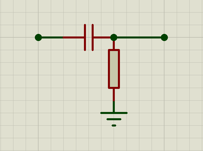
According to the formula fc = 1/2πRC, where the resistance is the input potentiometer of the amplifier (preamplifier). Accordingly, R is the nominal resistance of that potentiometer. Choose the capacitor so that the cutoff frequency is no higher than 30 Hz.
Important point: for proper playback you need a filter with a steep cutoff slope; otherwise, high‑frequency components of the signal can cause intermodulation distortion and overload the amplifier (preamp). To increase the cutoff steepness, use higher‑order filters.
The choice of filter order and cutoff frequency will largely depend on the amplifier (or preamp). For many transistor amplifiers, a first-order low-pass filter (LPF) won’t be sufficient, which can lead to noise and distortion. With tube amplifiers, a first-order LPF may be perfectly adequate.
When choosing a filter, it’s important to understand how the amplifier behaves at high frequencies. You can gauge this by changing the filter order and the cutoff frequency. You’ll need to strike a balance between perceived sound quality and distortion. If the LPF cutoff is set below 20 kHz, sound quality degrades significantly; set it too high, and you may introduce noise or clipping artifacts. Some amplifiers work fine with a first-order filter and a 40–50 kHz cutoff, while others require a second- or third-order LPF with the cutoff lowered to around 25 kHz. The lower the LPF cutoff, the more it affects the signal, because the roll-off is gradual and begins attenuating frequencies even before the nominal cutoff. For more detail, see this paper on low-pass filters.
Build Your Own DAC
At last, we’ve reached a DIY DAC build on a minimal budget. We’ll cover the designs from the simplest option to progressively more advanced ones.
Preamplification
When listening through a low-pass filter, the signal may be too quiet and need a volume boost. If your amplifier isn’t powerful enough, or you want to use headphones without connecting a power amp, you’ll need a preamp. Let’s look at the options.
Desktop build
For a stationary setup, step-up input transformers have proven to work best—like the one shown in the photo.
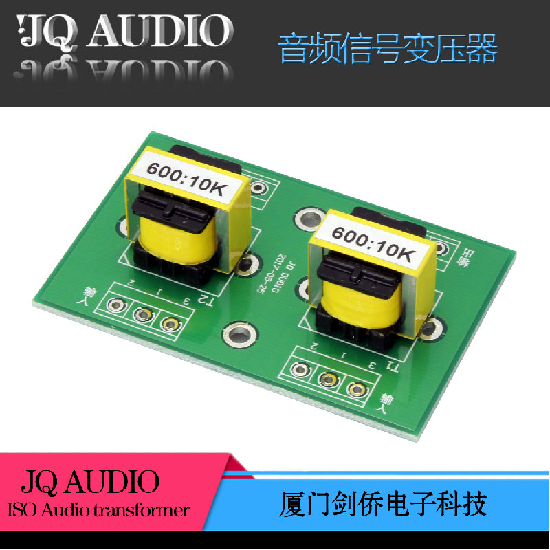
They increase the signal voltage by about four times, can be connected to balanced I/O, and have a 20 Hz–20 kHz frequency response. They cost around 2,000 rubles per pair; they’re among the cheapest transformers, but they get the job done.
Naturally, the transformer-based amplification approach has its drawbacks as well.
First, the price: these transformers are inexpensive, but a higher‑quality option can end up costing tens of times more.
Second, transformers only step up the voltage; you can’t use them on their own—only in tandem with an amplifier.
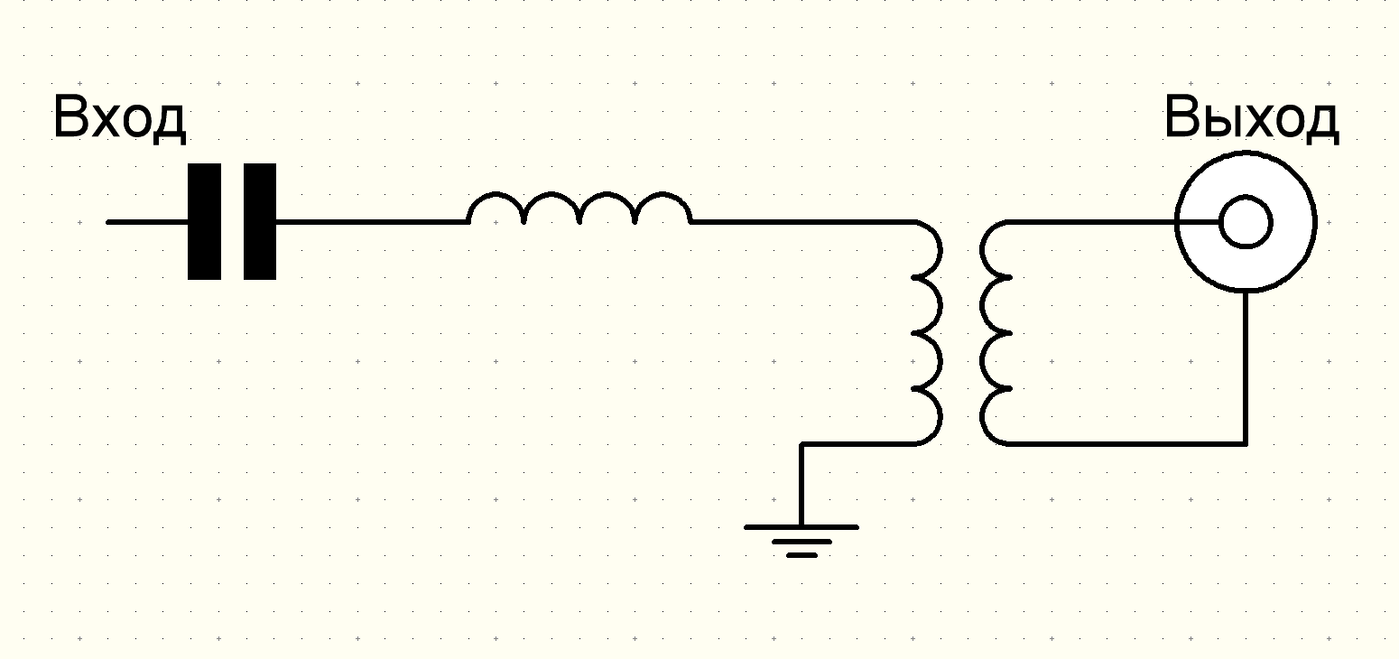
For proper operation, the DC component must be removed. Do this by inserting a series capacitor at the transformer’s input. The capacitor should have a sufficiently large capacitance, since together with the transformer’s input impedance it forms a high-pass filter (setting the cutoff frequency).
To calculate the capacitor value, take the transformer’s impedance—600 Ω in this case—and plug it into the formula fc = 1/2πRC; you should choose the cutoff frequency to be as low as practical. I used 22 µF capacitors, which gives a cutoff around 12 Hz.
Aim to use high-quality, low-ESR capacitors. They can significantly affect the signal, since it will be passing directly through them.
You’ll also need a low-pass filter (LPF) to suppress high-frequency noise. A first-order filter should be sufficient here. Transformers have a limited passband, and when combined with an LPF you get a steeper roll-off. With a transformer, it makes the most sense to use an RL filter (resistor and inductor), where the resistance R is the transformer’s input impedance, and the inductance is a coil of about 2.2–2.7 mH (millihenry).
You can calculate the inductive filter using this calculator.
This preamplification approach works well for stationary use, but few people would want to carry around transformers and an amplifier—even a small one. Let’s look at how to build a portable device that easily fits in a pocket.
Portable version
For a portable setup, the best choice is a preamplifier built around an IC with a single supply of no more than 5 V. To take the path of least resistance—both literally and figuratively—it’s ideal to combine everything in one: an active low‑pass filter and a preamp on an op-amp. You can design and calculate such a filter by hand, but it’s much easier to use online tools like Analog Devices’ Analog Filter Wizard or Texas Instruments’ Filter Design Tool. These web apps are straightforward: you just need to specify the following parameters:
- Filter type: Low-pass
- Gain: you can specify it in volts; it must not exceed the supply rails
- Passband: set the desired cutoff frequency
- Stopband: set it so the resulting filter is 2nd-order; otherwise you’ll need two or more op-amps
- Supply voltages: +Vs = 3–5 V, –Vs = 0 V
Based on the specifications, choose the chip the calculations will target. Done!
I used the Analog Filter Wizard, and this is the resulting circuit.
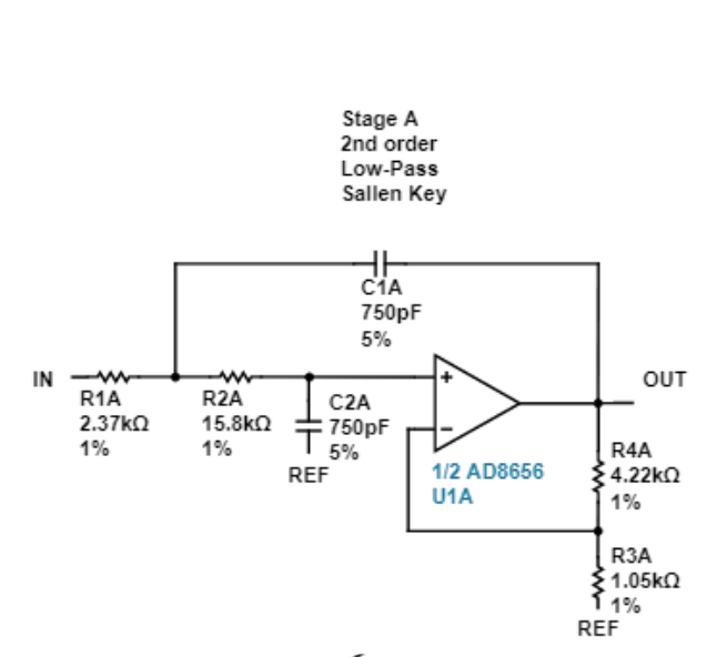
Specifications
- Supply voltage: +Vs = 3 V; –Vs = 0 V
- Gain: 3 V/V
- Passband: –3 dB at 35 kHz
- Stopband: –40 dB at 500 kHz
If you’re not into soldering or electronics, you can buy an off-the-shelf preamp with a filter, for example on AliExpress.
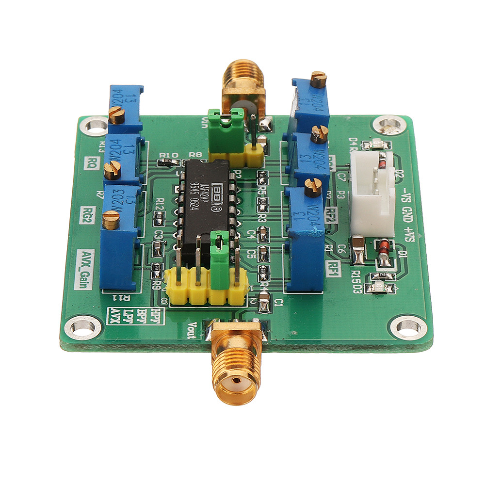
But be prepared to spend a bit more: you’ll need two of these filters, one per channel. Alternatively, you can buy a two-channel version.
It’s designed for a balanced connection, where each channel is carried separately over a three-wire scheme: one wire carries the main signal, the second carries the same signal in opposite phase (inverted), and the third is ground. So connecting it directly isn’t a great idea. However, you can generate the opposite-phase signal by inverting the DSD output using an operational amplifier, a Schmitt trigger, or a logic inverter.
It’s critical to obtain two identical signals that are 180° out of phase. Even minute mismatches will have a substantial impact on the output signal.
When selecting components, make sure to check the maximum operating frequency they support, because a DSD bitstream can range from 2,822.4 to 24,576 kHz. I also strongly recommend using galvanic isolation.
This is how to implement a balanced connection. You can also find other ready-made filter–preamplifier circuits online.
Building the Portable Version
If you’re not looking for the easy way out, let’s get to the build.
Hardware
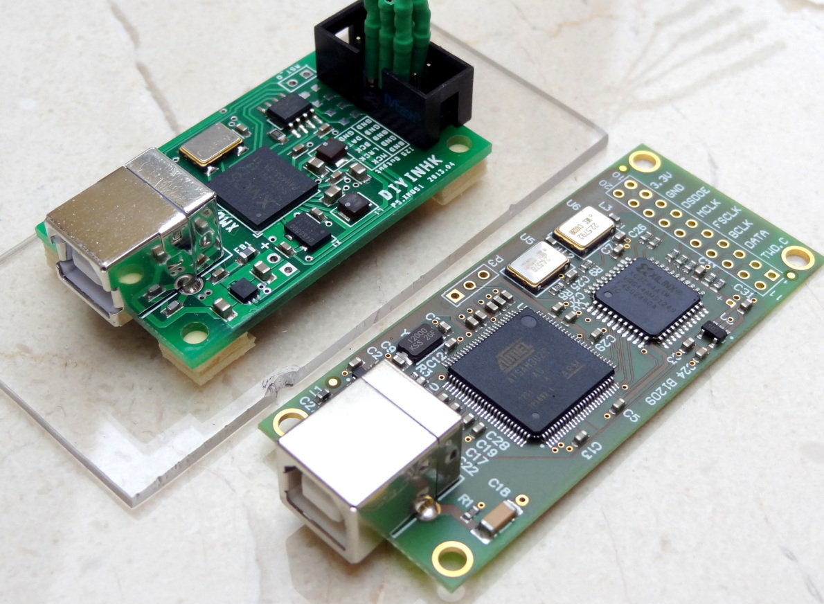
The following boards can be used as an I2S converter.
- Original Amanero. Costs around 7,000 rubles.
- Chinese clone using an ATSAM3U1C + XC2C64A board. The cheapest “replica” is about 2,000 rubles. It’s almost a 1:1 copy of the Amanero; the main differences are the PCB and component quality.
- Boards based on XMOS chips. Prices start at 1,700 rubles; the connection method is the same, but they have higher power consumption.
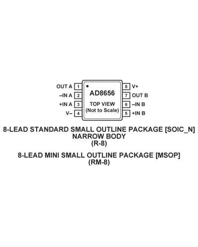
We use the AD8656 op-amp as the filter and preamplifier.
You’ll also need some passives—resistors and capacitors as specified in the schematic.

Ideally, use galvanic isolation for the FSCLK and DATA lines. Choose an isolator with some headroom on data rate—25 Mbit/s or higher—and a supply voltage in the 2.7–5.5 V range. Power the op-amp from a dedicated low-noise voltage regulator. You can add a series resistor at the input to limit the signal level, and a low-pass filter (LPF) on the output. That’s it!
The finished device is compact and can be connected to a phone or tablet via USB OTG.
Software
Windows drivers for the Amanero and the Chinese clone (ATSAM3U1C + XC2C64A) can be downloaded from the Amanero website. Linux and Android don’t require drivers; iOS likely doesn’t either.
There are dozens of mobile players that support Hi-Res PCM. However, with a filter-based setup you can only play DSD, so you need to convert PCM to DSD. Fortunately, there’s a player that does real-time conversion: Onkyo HF Player. It can convert MP3 and FLAC to DSD64 or DSD128. With Onkyo HF Player you can listen to virtually any music through a simple low-pass filter (LPF). It’s a pity the player isn’t free: it costs 699 RUB on Android and 749 RUB on iOS.
Playing back DSD through a low-pass filter has an edge over the traditional approach of using a DAC.
First, it sounds much better than with many DACs.
Why is that? The core of a delta-sigma DAC is its digital signal processing. Think of it as a complex digital filter with heavy oversampling, a 5th–7th‑order modulator, plus dithering and/or noise shaping. That demands substantial compute, which is constrained inside a DAC, whereas modern smartphone processors have far more to spare. As a result, a smartphone can implement higher‑quality digital filtering and modulation.
Why manufacturers don’t put powerful processors inside DACs is a mystery. Maybe it’s cost-cutting, or maybe they believe processing should live in a separate box. For example, Asahi Kasei Microdevices (AKM) offers standalone DSPs that handle conversion, including oversampling, and separate DACs with a bypass mode.
Second, playing back DSD through a low-pass filter is significantly cheaper, since a good DAC—even a budget Chinese one—will cost much more.
Bottom line
Pros
- You can easily build this yourself, even if you’re a beginner electronics hobbyist.
- Supports connection to mobile devices.
- Prices start at 2,000 rubles.
- On a phone with a 3,200 mAh battery, this DIY DAC ran for over six hours of playback with real-time PCM-to-DSD conversion.
- In my experience, it sounds better than many high-end DACs.
Drawbacks
- The output is single-ended, so the noise will be correlated with the primary signal.
- At low signal levels, minor distortion may occur.
Building the Desktop Version
This approach will be much harder to implement, but it’s worth it.
Hardware
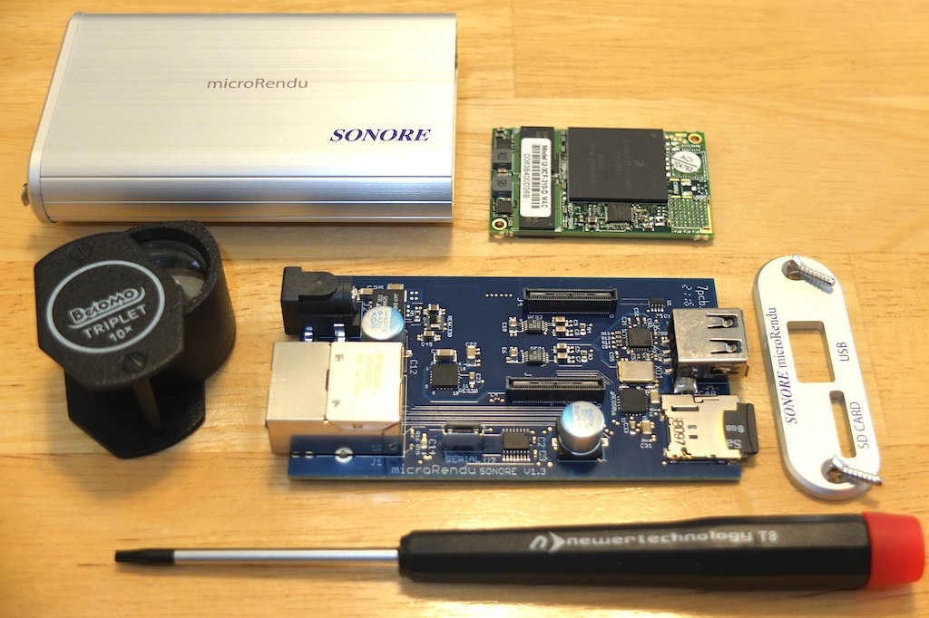
The best results will be achieved by using a BeagleBone Black or BeagleBone Green as an I2S converter.
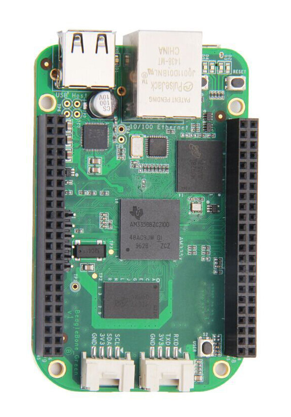
The BeagleBone is the only single-board computer with an open-source driver that supports using an external clock generator. You can feed that external clock to both the converter and, if present, the DAC. This helps reduce I2S transmission errors. It also lets you choose whatever clock quality and frequency you need.
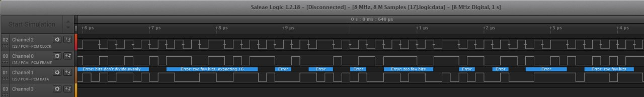
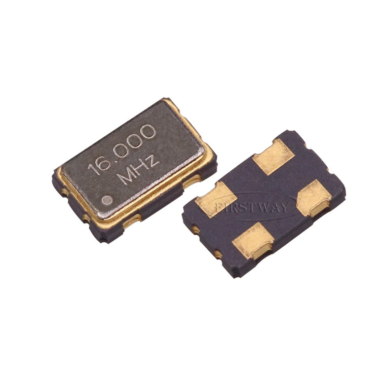
A DAC isn’t required for DSD playback in this configuration. However, you must use high‑quality 45.1584 MHz and 49.152 MHz clock oscillators for DSD256 and DSD512, because the 1‑bit stream runs at 11.2896 MHz and 22.5792 MHz, respectively. The master clock (MCLK) should be at least twice the data rate, otherwise transmission errors may occur.
External Clock
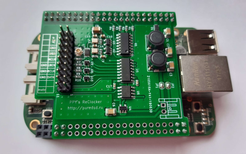
The first thing you’ll need is an external clock generator—just a “clock” in common parlance. As usual, you’ve got two options: if you’re handy with a soldering iron, you can build one yourself; if not, buy an off-the-shelf unit.
Pavel Pogodin has a project called DSC — a DAC released under an open license. The site hosts documentation for Pavel’s DAC, and you’ll also find a reclocker schematic for the BeagleBone. That design supports external clocks and automatically switches between the 44.1/48 kHz clock families. You can use it as a starting point to build something similar.
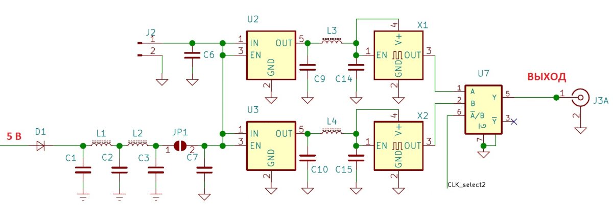
This board is designed to handle both PCM and DSD playback, but if, like me, you’re only interested in DSD, you can get by with just the following section of the circuit.
info
All reference designators and component values are provided in the documentation (PDF).
And of course, the simplest—but costliest—option is to buy off-the-shelf generators.

If you want the generator to auto-switch between the 44.1/48 kHz clock families, you’ll need to break out the soldering iron and install the U7 selector (74AUP2G157) shown in the schematic above—otherwise you’ll be switching oscillators by hand. For example, CD‑DA, MP3, and DSD only need a 45.1584 MHz oscillator, but if you want to listen to vinyl rips at 96 or 192 kHz, you’ll also need a 49.152 MHz oscillator.
After connecting the clock generator to the BeagleBone Black (pin P9_25), the only thing left is to bring out the two DSD channels (pins P9_30, P9_41).
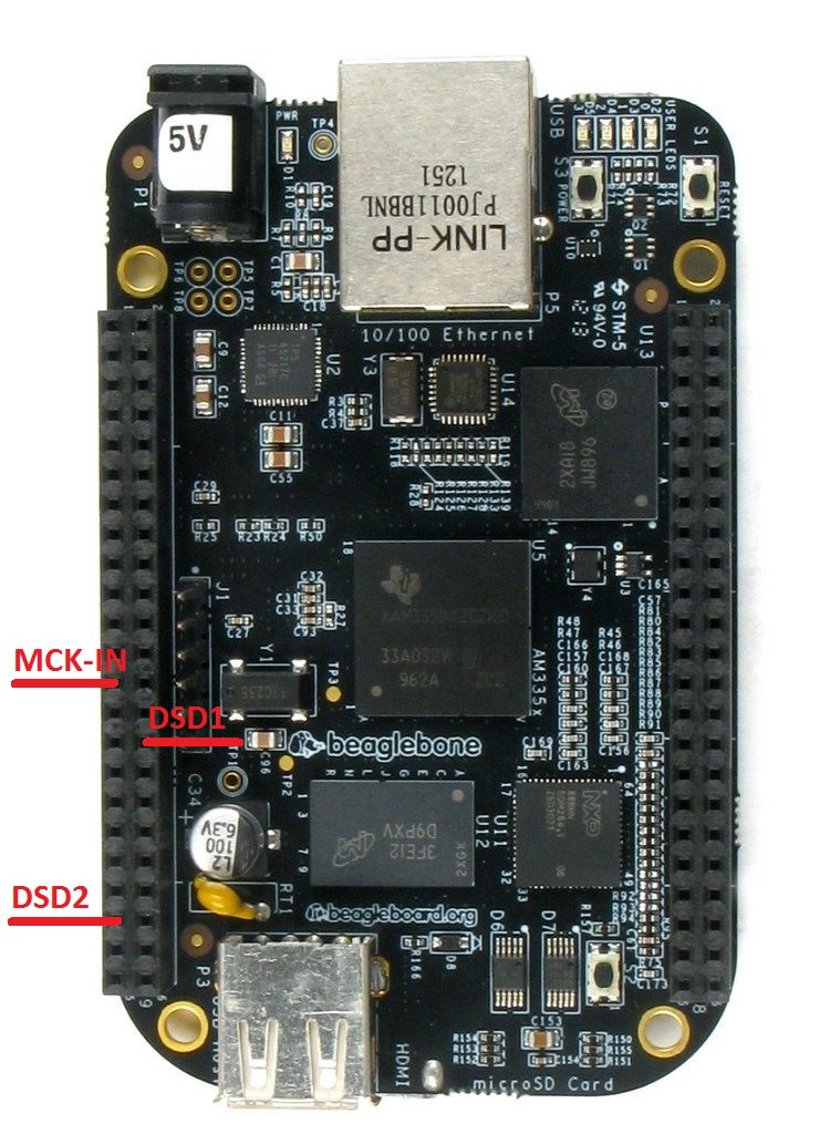
The pin numbers are provided for the mini Botic7 distribution (archive) built by Pavel Pogodin. Connect a filter to the DSD1 and DSD2 pins, and the device will be ready to use.
Software
Let’s move on to the software side. We’ll start with the driver.
There’s an open-source driver for the BeagleBone Black/Green written by a diyaudio.com forum member known as Miero.
The driver has plenty of settings, all documented on the website: site. You can change them in the / config. For example, you can route PCM and DSD to different pins, set the LRCLK frame length (useful for multibit DACs), or specify a particular clock generator frequency.
In our case, there’s nothing to change. Just download the BeagleBone Black firmware (archive); it already includes the driver. Write the downloaded image to a microSD card using dd on Linux or Rufus on Windows. Insert the card into the board’s microSD slot, hold the button next to the slot, and power it up. After a few seconds, release the button. The board should start booting, with the status LEDs blinking to indicate activity.
By default, the profile with the HQPlayer client will be loaded—that’s exactly what we need. You can also copy the firmware to the BeagleBone Black’s internal storage; instructions are available on Pavel Pogodin’s website.
HQPlayer is the best option for PCM-to-DSD conversion thanks to its extensive set of modulators and digital filters. It supports 11 sigma-delta modulators, 30 digital filters, oversampling up to 98.304 MHz (DSD 2048), and NVIDIA CUDA acceleration.
Of course, oversampling to DSD 2048 is overkill—especially in our setup: the BeagleBone Black and Amanero can handle at most DSD 512. On top of that, many computers won’t manage even DSD 256 when using “heavy” digital filters with complex modulators. HQPlayer’s digital filters are very high quality and require substantial processing power.
This player has its downsides. First, it’s paid software—and not exactly cheap; second, it supports a very limited set of formats: CDDA, FLAC, DSDIFF, DSF, RIFF, AIFF—and, unfortunately, it doesn’t support CUE. That said, you don’t have to buy it. The trial lets you listen without restrictions for 30 minutes, then simply exits. And nothing stops you from launching it again and using it in 30‑minute chunks as many times as you like until you get tired of it.
Its flexibility and excellent sound easily outweigh any shortcomings. The player delivers very high‑quality audio. The digital filter and modulator are the core of a sigma‑delta DAC, and this player implements multiple variants of both, letting you dial in processing quality to match your computer’s performance. When used with a BeagleBone Black or an Amanero, HQPlayer effectively becomes a finely tunable sigma‑delta DAC, leveraging your computer’s considerable processing power.
To connect to a BeagleBone Black, go to HQPlayer settings and select NetworkAudioAdapter in the Backend drop-down. In the Device list you should see “Botic7: Botic,” provided the HQPlayer host and the BeagleBone are on the same subnet and there’s a DHCP server. Set Default Output Mode to SDM (DSD). For Bit rate (/limit), a good starting point is 44.1k x64. Note that the settings screens differ between versions 3 and 4 of the player.
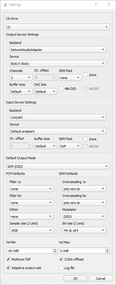
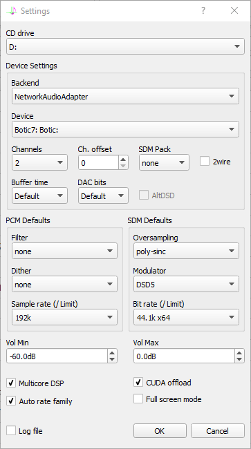
You can fine‑tune the remaining settings empirically—adjust to taste (by ear) and to what your computer can handle.
Now connect a low-pass filter to the BeagleBone Black’s DSD outputs. To suppress power-supply noise and LED ripple, it’s best to use galvanic isolation. That’s it—the device is ready!
Bottom line
Pros
- The build ended up being almost open source: BeagleBone Black started as an open project; the official site provides documentation and a full schematic of the microcomputer; the I2S driver’s source code is publicly available; and the reclocker (clock generator) schematic is also published under an open license. The only proprietary component here is HQPlayer—too bad there’s no open-source alternative.
- A BeagleBone Black will run about 3,800 rubles; oscillators and consumables start at 600 rubles.
- The device delivers excellent sound, especially when playing native DSD or converting PCM via HQPlayer.
Cons
The only issues were with the player; I’ve already listed them.
The DSC Project and FPGAs
When you reconstruct through a low-pass filter, there’s just one downside—the output is essentially one-bit. But with a high sampling rate the noise impact is negligible, and with some additional effort you can solve that issue as well.
Pavel Pogodin’s DIY DSC DAC project could be a high-end alternative to DEM. However, a commercial DAC built to Pogodin’s design will likely be on the expensive side. Even the early Chinese DIY boards based on the first DSC revisions cost over 10,000 rubles—and that’s before you factor in the price of precision components, the power supply, and the enclosure.
Sure, you can save up and wait for the DAC to come out, but that doesn’t work for me. So I decided to port the DSC project to an FPGA (field‑programmable gate array). I hope Pavel won’t take offense about it. 🙂
For the build I’ll need an FPGA. I chose one of the cheapest options—the Altera MAX II (EPM240T100C5). It has 240 logic elements and 100 pins. By modern FPGA standards that’s modest, but the price is modest too—starting from about 500 rubles.
We used the DSC 2.5.2/2.6.2 schematic as the basis (PDF).
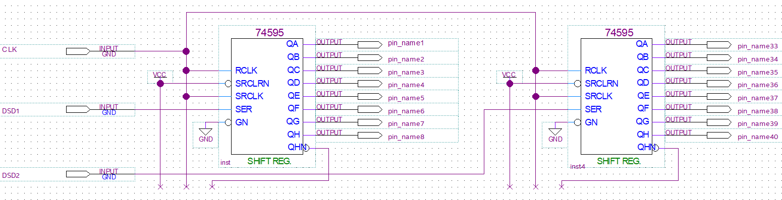
The DSC project is built around the 74AHCT595 shift register; eight of these registers make up a single audio channel, either right or left. The first four are daisy-chained, forming one large shift register with 32 parallel outputs—these four generate the positive phase. The other four are chained the same way and generate the negative phase. The first four receive the DSD bitstream as-is, while the other four receive the same data inverted. Resistors on the parallel outputs are summed into two buses—one for the positive phase and one for the negative—which together form a balanced audio output.
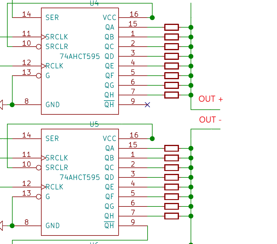
A DSC operates much like a multibit DAC, except the outputs update continuously rather than once per LRCK frame, and every data bit has the same weight. In essence, the DAC’s output is the sum of the individual signals coming from the register outputs.
Schematic Design
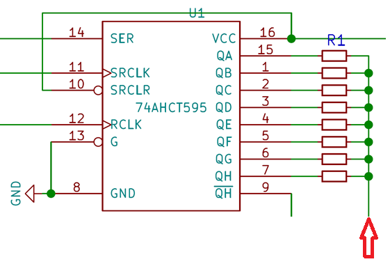
The Quartus Prime development environment—where we’ll compile the FPGA firmware—includes a ready-made model of the shift register, specifically the same one used in the original DSC: the 74AHCT595.
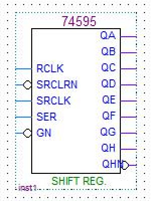
Quartus Prime also lets you build your logic design entirely through a graphical interface, without learning any HDLs or programming. Creating the schematic is as easy as using a standard schematic-drawing tool.
There’s a catch: the original DSC design won’t fully fit into the chosen Altera MAX II CPLD, so we’ll have to simplify it. The MAX II has only 100 I/O pins (and not all of them are usable), while the DSC needs at least 128. So we’ll have to give up the balanced output. I’ll explain how to build the full version a bit later. For now, we’ll leave out the shift registers for the negative path and the extra logic used solely for signal inversion.
All that’s left is to assign the I/O pins, compile the project, and program the FPGA.
After flashing the bitstream, connect resistors to the FPGA pins and tie their outputs together according to the original DSC schematic.
Next, connect a low-pass filter (LPF) and a capacitor to the resistors’ common output node to suppress unwanted high-frequency components and remove the signal’s DC component.
Connect the LPF output to the amplifier, and feed DSD into the input pins from a BeagleBone Black or an Amanero. The lightweight version of the DSC project is ready!
Stereo Project in Verilog
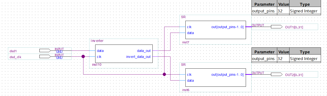
To optimize and expand functionality, I migrated the DSC logic to Verilog HDL. As a result, the number of logic elements used on the FPGA was almost cut in half. For clarity, I built a mixed design: the top level is a schematic, while the nested blocks are implemented in Verilog code.
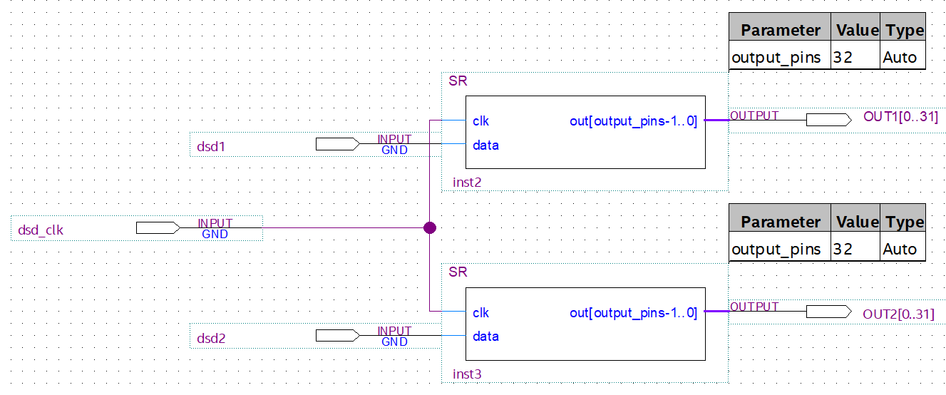
SR blocks are shift registers; compared to the 74AHCT595, they’re much simpler. In Verilog, their code looks like this:
module SR #(parameter output_pins = 32)
(
  input clk, data,
  output [0:output_pins-1]out
);
reg [output_pins-1:0]data_reg;
always @(posedge clk)
data_reg <= {data_reg[output_pins-2:0], data};
assign out = data_reg;
endmodule
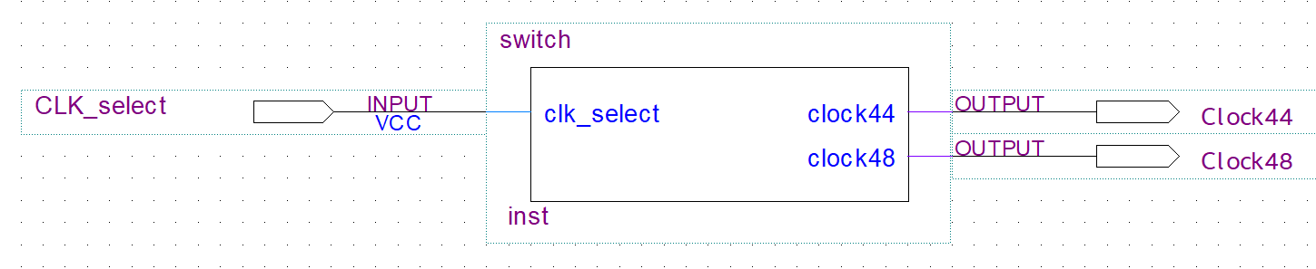
In this version, a selector was added specifically for the BeagleBone Black to switch between external oscillators. Most high‑quality clock oscillators have an enable/control pin: when the pin is driven high, the oscillator runs; when it’s low, it’s disabled. The control pin is usually located near the “key” mark—a small dot in one corner of the package.
Thus, by tying the outputs of two oscillators together through 33 Ω resistors, you can switch between the required sample-rate family. Below is a module that toggles the pin states based on the sampling rate. Connect the P9_24 pin on the BeagleBone Black to the CLK_select pin on the FPGA, and route the Clock44 and Clock48 outputs to the oscillators’ control inputs.
Source code:
module switch(
  input clk_select,
  output clock44,
  output clock48
);
assign clock44 = clk_select ? 1 : 0;
assign clock48 = clk_select ? 0 : 1;
endmodule
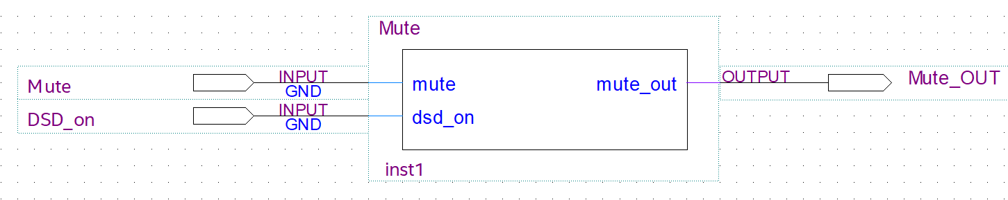
To enable automatic mute/unmute of the audio output, a Mute logic circuit has been added in line with the original DSC schematic.
Source code:
module Mute(
  input mute,
  input dsd_on,
  output mute_out
);
assign mute_out = ~(mute | ~dsd_on);
endmodule
The Mute element only implements the logic for toggling the Mute_OUT line; to make muting actually work you need hardware that disconnects the DAC’s audio output. There are various ways to do this. For example, DSC v2.5.2 uses a controlled analog switch. What you use is a matter of preference. You can also skip Mute entirely—nothing critical will happen—though you’ll hear occasional single clicks when manually switching tracks.
Verilog Design (Mono)
I’ll show a DSC implementation that’s as close to the original as possible. Remember, the original design wouldn’t fit on the MAX II because it didn’t have enough output pins?
There are two ways to solve this: either buy an FPGA with more I/O, or buy two FPGAs and implement the right and left channels separately. A single FPGA with enough outputs is much more expensive than two Altera MAX II devices, so the choice is obvious. There’s also a belief that dual mono—two fully independent mono paths—sounds better than standard stereo. Now we’ve got a great excuse to put that claim to the test!
So we need to build a stage that inverts the signal and, crucially, provides synchronous outputs, because in a balanced design even small mismatches can strongly affect the audio signal.
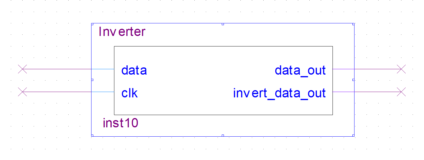
Feed the DSD right- or left-channel data into data, and the DSD clock into clk. The outputs provide the non-inverted and inverted DSD data streams.
module Inverter (
  input data, clk,
  output reg data_out = 0, invert_data_out = 0
);
reg check = 0;
always @(posedge clk)
begin
  if(data) check = 1;
  if(check)
  begin
    data_out <= data;
    invert_data_out <= ~data;
  end
end
endmodule
Next, as in earlier versions, connect the component we just created to the shift registers.
Solder resistors to the shift-register outputs as in the original schematic. This yields a balanced output. The first FPGA handles the right channel in dual-mono, and the second FPGA handles the left. Connect the BeagleBone Black outputs P9_30 (DSD1) and P9_41 (DSD2) to the DSD1 input on the first FPGA and the same input on the second FPGA. The microcomputer output P9_31 (BCK) is shared by both FPGAs; connect it to the dsd_clk input.
I’m not listing the FPGA pin assignments, because the projects will likely be updated and the numbers may change. To look them up—and adjust them for your needs if necessary—open the project in Quartus Prime.
For the output resistors, it’s best to use off-the-shelf resistor networks (arrays). High-precision arrays are available and can further improve sonic performance. Connect the transformers to the common node of the resistor network, as in the original DSC.
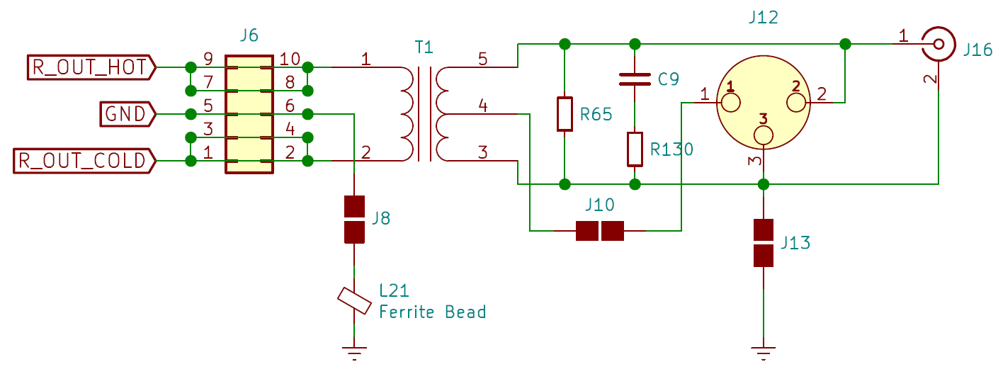
- R_OUT_HOT — input to the first register bus.
- R_OUT_COLD — input to the second register bus.
Alright, we’ve built a project that’s as close to the DSC as it gets! Hopefully it won’t be far behind the original in terms of sound. Ideally, the power supply should be redesigned, but even on my test FPGA with 1% resistors and a standard switching PSU, it sounds great. And with a quality power supply and precision resistors, it’ll be even better!
Bottom line
Pros
- Price starts at 600 rubles, plus the cost of a BeagleBone Black or an Amanero.
- Sound quality is even better than playing DSD through a low-pass filter.
- Full customization with the ability to add new processing algorithms.
- Significantly easier to implement compared to the original DSC.
Cons
No downsides identified (at least for now).
Conclusion
I’m convinced that listening with on‑the‑fly PCM-to-DSD conversion is the best way to play mainstream formats, especially when using a DSC. The only real alternative is to promote wider adoption and continued development of the formats themselves—DSD in particular.
To be honest, no matter what digital filters, sampling rates, or modulators I’ve tried, native DSD still sounds better. Plus, during playback it doesn’t need any digital processing at all: no filters, no modulators, no noise shaping—partly because that processing was already done during recording.
But in theory, with a quality comparator and a high clock rate, you can achieve something akin to analog recording without any digital processing at all. It’s a pity that DSD isn’t as widespread as CDDA or even FLAC. Honestly, the desire to help popularize the format—at least a little—was the main motivation for writing this piece. I hope you enjoyed it.