Today, one of the most popular SDR systems is a made-in-China RTL-SDR dongle that features a truly fantastic capacity (especially taking its modest price).
Its RTL2832 + RT820 scheme is shown below.
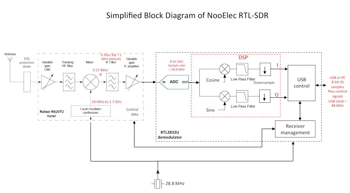
The signal enters the input of the radio path implemented on the RT820 chip, and the first frequency conversion (to the intermediate frequency of 3.57 MHz) is performed there. Concurrently, the image channel is suppressed as much as possible with filters.
Such a decision makes it possible to cover a very broad range: from a few tens of megahertz to a couple of gigahertz. Of course, the device cannot embrace the entire range at once – only in ‘segments’ several megahertz in size. According to the documentation, RTL2832 can digitize a signal with the frequency of a few tens of megahertz, but this capacity is limited by the USB bandwidth. However, in many real-life situations, this is more than enough.
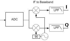
The resultant IF signal is digitized by RTL2832, and then the second frequency translation is performed at the software level. A software quadrature mixer implemented as a scalar product of the incoming signal to the reference signal is used for this purpose. And in the case of the quadrature mixer, two signals having the same frequency but displaced in phase by π/2 are used as the reference signals. At the output of the mixers, low pass filters are installed: they filter the signal with a double reference frequency. As a result, there are two signals at the output: an in-phase signal (I) and a quadrature signal (Q). Although all these terms are somewhat conventional…
The signals are transmitted via USB as a data flow. Prior to the transmission, the resampling takes place, and the data transmission rate drops to some 2 MSa/s – this is the ‘bottleneck’ of the scheme. Why a quadrature mixer is used? Because, according to the digital signal processing theory, the I and Q signals are sufficient to decode a signal with any modulation type. However, this article is mostly focused on amplitude modulation (AM), which is implemented in the simplest way.
Imagine that I is the real part and Q is the imaginary part of a complex signal (Z). If so, then the target demodulated signal is: |Z| . Frequency modulation and phase modulation are more sophisticated topics (as the entire digital signal processing theory is); so, if you are really interested in this subject, I suggest reading special literature.
Then the signal is processed by the computer that uses individual I and Q samples to produce a complex sample Z . As you understand, this is also a conventionality making it possible to apply the mathematical tools to the signal.
The above operations are performed using special software packages: SDR# (Windows), gqrx (Linux), and GNU radio (Linux). The last one is of utmost interest: not only does this program allow to go through the entire frequency range, but also visualizes the internal structure of a software defined radio. Most importantly, you don’t have to review sophisticated program code; instead, you just use the mouse to create a graph consisting of individual blocks. The picture below shows how a simple RTL-SDR-based FM radio receiver looks in GNU radio.

RTL-SDR acts as a source that generates a flow of complex Z values (this equals to both I and Q flows). Then the signal goes through a digital low pass filter (LPF) that separates the frequency band that is of interest to the user. In this particular case (frequency modulation), I need a frequency band of ~200 kHz with the center in the zero point, and the frequency set on the RTL-SDR must correspond to it. Then the signal reaches to the frequency detector that generates at the output a real sound signal suitable for an audio card. The resampler is required to adjust the signal bitrate. Overall, a half of the radio receiver is created with just a few mouse clicks.
Simple SDR
In the past, SDR radio systems using a PC sound card as an analog-to-digital converter (ADC) were pretty common. The majority of such devices had the same structure and consisted of a reference generator, a phase shifter, a mixer, and a low-frequency amplifier. The amplifier’s output was connected to the sound card’s line input. As you can see, the scheme was similar to the above-mentioned RTL2832; the only difference is that the intermediate frequency in RTL2832 is lower, and the quadrature signal is digitized.
Below is the functional scheme of a popular ZetaSDR receiver.

The signal from the clock generator with the F frequency is sent to the phase shifter implemented on the basis of two D flip-flops combined together into a Johnson counter. The counter is a shift register whose last inverted output is sent to the input. When a clock signal is applied, waves of zeros and ones are alternately spread through the outputs of the shift register. In this particular case, states 00, 01, 11, and 10 will be sequentially set at the Q0 and Q1 outputs; in the decimal system, this corresponds to 0, 1, 3, and 2. For the signals, these are two meanders phase-shifted by 90° with the frequency of F/4.

Then the reference signals arrive to the Dan Tayloe’s mixer implemented on the basis of a 74HC4052 analog multiplexer. The mixer multiplies one signal by the other one because if one of the signals is a meander, the multiplication comes down to a simple switching.

Below is a diagram illustrating the multiplexer operation: a high level at a channel conventionally corresponds to an active channel.

If I assume that the X0 channel corresponds to 0°, then 90° corresponds to X1, 180° to X3, while 270° to X4. Operational amplifiers are connected accordingly. As a result, I receive at the output the I and Q signals shifted by 90°. More information on the mixer can be found in the original article by Dan Tayloe. Then the signals are transmitted to the sound card’s line input.
Synthesizer
ZetaSDR uses a fixed-tuned oscillator; this provides a reception bandwidth equal to the bandwidth of the sound card around the F/4 range. Of course, this is not much because audio cards rarely support bandwidths over 200 kHz. On the other hand, ZetaSDR was designed as an observer receiver, and its 200 kHz range covers the entire amateur radio frequency band with the wavelength of 40 m. But my goal is to cover several short-wave bands! Fortunately, in the past ten years, the situation with synthesizers has improved greatly.
I am going to use the SI5351 microchip – i.e. a clock generator having a digital interface and able to generate several signals with frequencies from 8 kHz to 160 MHz. The only required external component are a quartz and two pull-up resistors for I2C. For lazy hackers, Chinese online stores offer completely assembled modules on this chip, which is very convenient for prototyping.
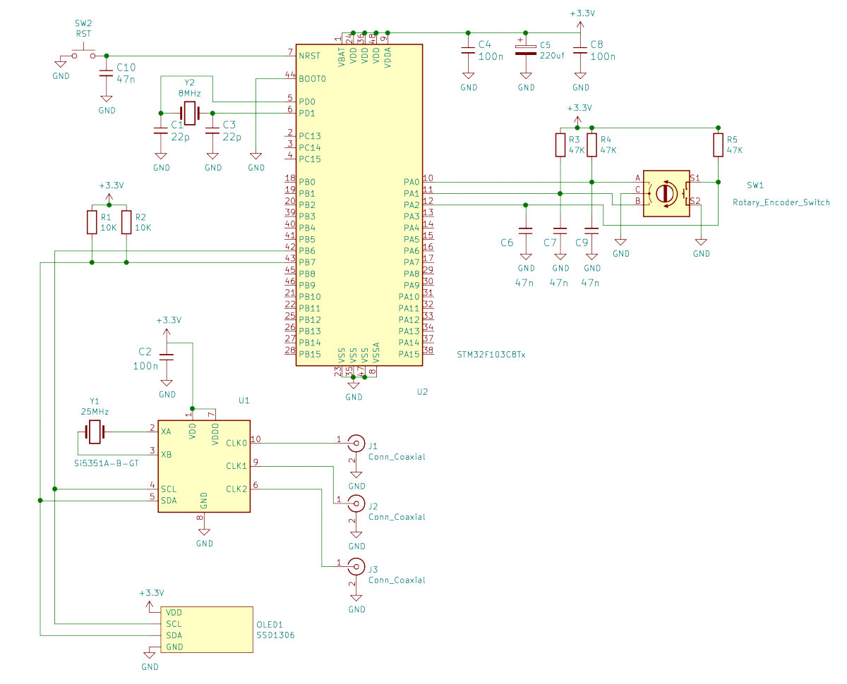
I will use STM32F103C8T6 as a microcontroller (it’s very popular nowadays thanks to the Bluepill board). So, I assemble the prototype on Bluepill and the SI5351 module and use an I2C OLED display and an encoder as the interfaces. The resultant scheme looks as follows:
I use the STM32-SI5351 library for communication with SI5351. This is a port of a similar library originally written in Wiring for Arduino and recoded in C. The library uses the HAL code, while I am accustomed to LibOpenCM3 functions; so, I have slightly adjusted its source code. Basically, the changes affect the data sending and reading functions. In addition, I had to add the static modifier before the private variables; otherwise, it could not be compiled.
The adjusted functions look as follows:
/** Write multiple bytes * @param regAddr Register address to write to * @param length Count Bytes * @param data Value to write * @return Status of operation (true = success) */uint8_t si5351_write_bulk(uint8_t regAddr, uint8_t length, uint8_t *data) { uint8_t temp[255]; temp[0] = regAddr; memcpy(temp+1,data, length); i2c_transfer7(SI5351_I2C, SI5351_BUS_BASE_ADDR, temp, length + 1, 0, 0); return 1;}/** Write single byte to an 8-bit device register. * @param regAddr Register address to write to * @param data New word value to write * @return Status of operation (true = success) */uint8_t si5351_write(uint8_t regAddr, uint8_t data) { uint8_t temp[2]; temp[0] = regAddr; temp[1] = data; i2c_transfer7(SI5351_I2C,SI5351_BUS_BASE_ADDR, temp, 2, 0, 0); return 1;}uint8_t si5351_read(uint8_t regAddr) { uint8_t reg_val = 0; i2c_transfer7(SI5351_I2C,SI5351_BUS_BASE_ADDR, ®Addr, 1, ®_val, 1); return reg_val;}Due to the discrepancies in data processing during the transfer between HAL and LibOpenCM3 via I2C, the modified si5351_write_bulk ( function is somewhat complicated. But taking the small amount of data transmitted to SI5351, I decided not to go a level down and write a handmade analogue for i2c_transfer7 (. The header file was the most labor-consuming. To launch the synthesizer, I had to initialize SI5351, enable the respective port, and set the frequency.
si5351_init(SI5351_CRYSTAL_LOAD_10PF, 25005500, 0);si5351_drive_strength(SI5351_CLK0, SI5351_DRIVE_8MA);si5351_set_freq(freq_khz * 100000ULL, SI5351_CLK0);The frequency is set in si5351_set_freq ( in hundredths of a hertz; so, values expressed in kilohertz are multiplied by a constant. It is also important to specify the constant type: ULL (uint64). Now the microcircuit can synthesize an arbitrary frequency and generate several signals with a preset phase shift. The function generating two reference signals with a phase shift of 90° has been implemented as follows:
void set_feq_90(uint64_t freq) { uint8_t coef = 650000000 / freq; uint64_t pll_freq=coef * freq; // We will output 14.1 MHz on CLK0 and CLK1. // A PLLA frequency of 705 MHz was chosen to give an even // divisor by 14.1 MHz. unsigned long long freq = 14100000 00ULL; unsigned long long pll_freq = 705000000 00ULL; // Set CLK0 and CLK1 to output 14.1 MHz with a fixed PLL frequency set_freq_manual(freq*100, pll_freq*100, SI5351_CLK0); set_freq_manual(freq*100, pll_freq*100, SI5351_CLK1); // Now we can set CLK1 to have a 90 deg phase shift by entering // 50 in the CLK1 phase register, since the ratio of the PLL to // the clock frequency is 50. set_phase(SI5351_CLK0, 0); set_phase(SI5351_CLK1, coef); // We need to reset the PLL before they will be in phase alignment pll_reset(SI5351_PLLA);}Initially, I used only this function, and my first receiver prototype had no phase shifter. However, the addition of a 74AC74-based local phase shifter improved the result, and I abandoned the idea to generate two signals (even though this variant was workable as well).
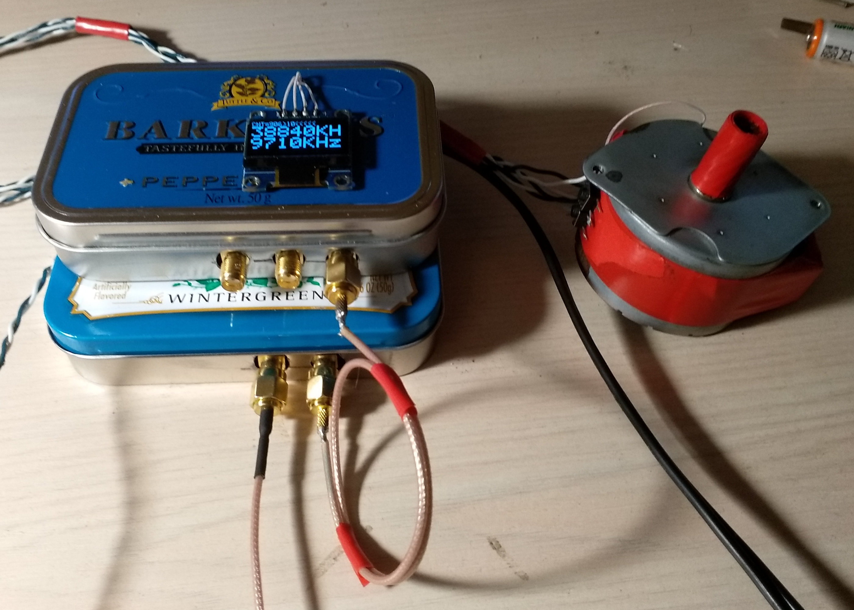
I use an SSD1306-based OLED screen as a display; a special library implementing the formatted text output and supporting (to a limited extent) Unicode has been written for it. But the encoder became a true problem. Initially, it seemed to be very handy for frequency tuning. But a cheap contact encoder started malfunctioning pretty soon and became unusable. So, I had to find a ‘permanent’ solution, like it was in Bruker AC200. And I found it!
The point is that an encoder can be produced on the basis of a stepper motor – and I had one from a printer. So, I slightly adapted the scheme for HEF4011 that I had and assembled the scheme shown below. The Schmitt triggers assembled on inverters produce the digital output.
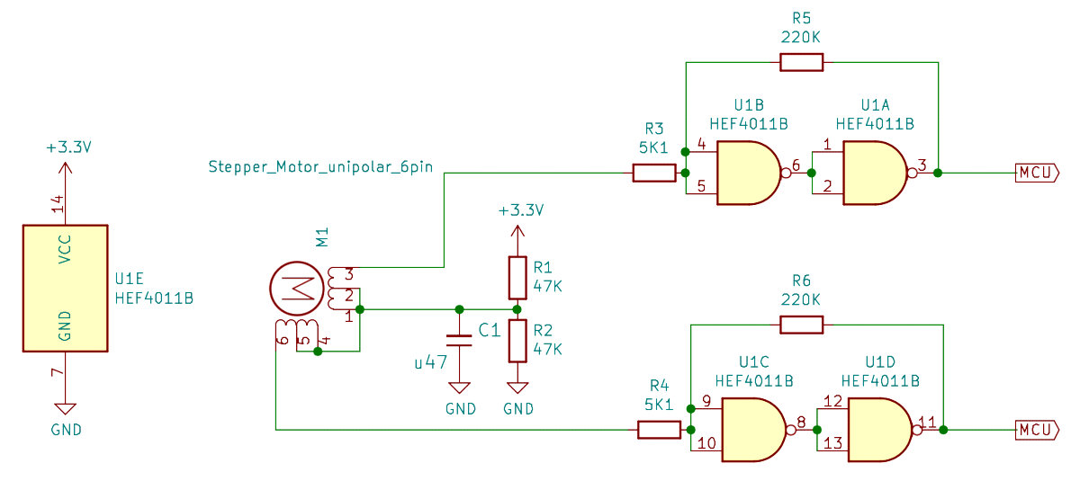
The decryption algorithm for the encoder’s signal is elegant and simple. An interrupt occurs on the rising edge of one of the encoder’s outputs, and the level at the second output is determined by the interrupt handler function. If there is zero, then I assume that the encoder rotates forward; if there is one, it rotates backward. The graph below demonstrates the algorithm.

As you can see, there are quadrature signals again: in one case, the phase is 90° behind, while in the other case, it is 90° ahead.
The algorithm had worked smoothly with the contact encoder; however, I encountered a problem with the stepper motor: it was making two steps at once. In addition, after changing the direction, the motor had performed the first step incorrectly. I solved the first problem at the software level by simply skipping odd interrupts; with regards to the second bug, I just ignored it.
void exti0_isr() { static uint8_t n = 0; n++; if (n % 2) { exti_reset_request(EXTI0); return; } if (gpio_get(GPIOA,GPIO1)) { if(encoder < MAX_LIMIT - coef) { encoder += coef; } } else { if (encoder > MIN_LIMIT + coef) { encoder -= coef; } } // Interrupt flag has to be reset manually exti_reset_request(EXTI0);}Interestingly, the interrupt only works when the output is configured as a float input; it doesn’t work when output is configured as input pullup/pulldown (even though, in theory, it should). Buttons are used to fast switch between frequency tuning intervals and set the frequencies corresponding to short-wave bands. As usual, the synthesizer source code is available on GitHub.
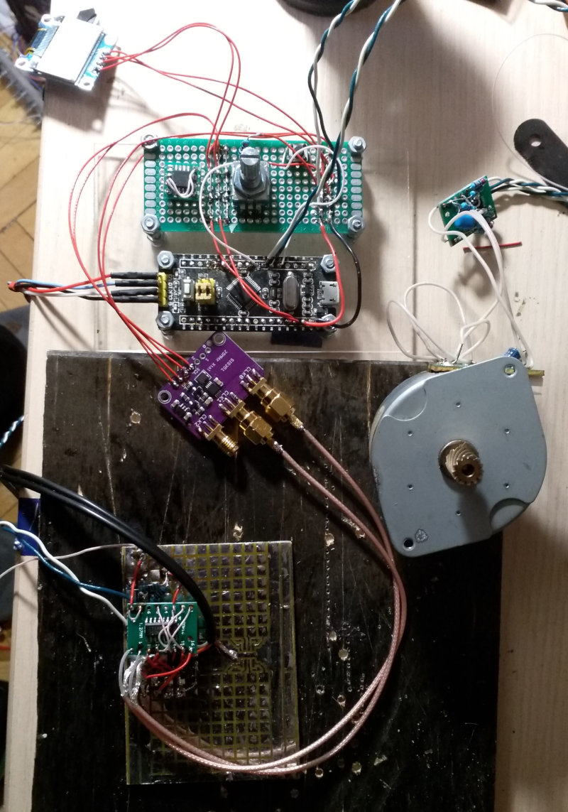
Assembling the receiver
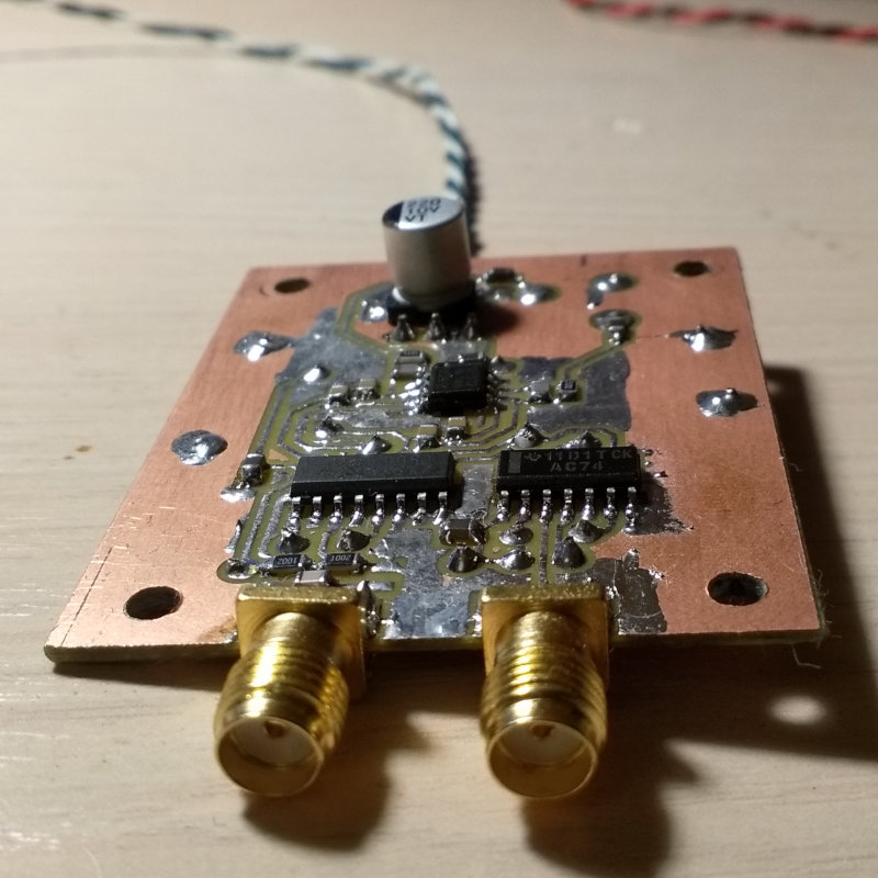
My scheme is slightly different from the reference one.
Initially, the receiver and synthesizer were assembled on mounting boards. The first version had no phase shifter, and both reference signals were generated in SI5351.
Then I added a makeshift phase shifter. Surprisingly, but the device was working! You can also use 74HC74 instead of 74AC74, but in that case, you likely won’t be able to go over 10 MHz because 74HC74 operates at frequencies up to 40 MHz. By contrast, the AC series supports frequencies up to 120 MHz.
After making sure that the device was operational, I reassembled it on printed circuit boards. This has slightly improved the signal quality, especially after shielding the boards – even though the difference was not drastic.
High-frequency signals should be transmitted by a coaxial cable using proper connectors, such as SMA. At worst, the cable can be soldered. The cable connected to the audio card must also be shielded. You don’t necessarily have to use a high-frequency cable, but it definitely must be shielded; otherwise everything would be swamped in the interference.
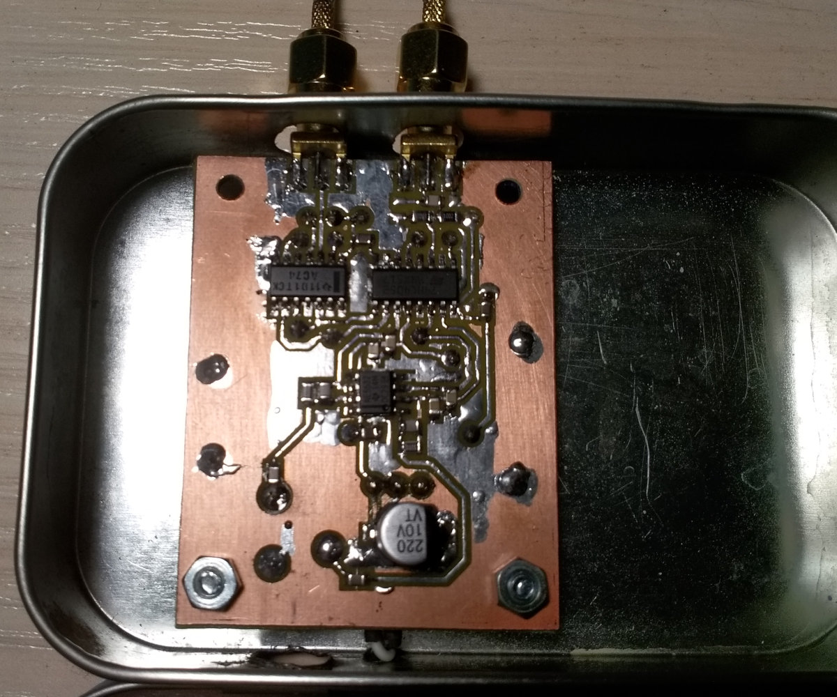
The printed circuit boards are made of double-sided foil-clad fiberglass; the copper layer on the back side is preserved and connected to the ground; the jumpers are made of insulated wires; and the holes are countersunk at the entrance to the board.
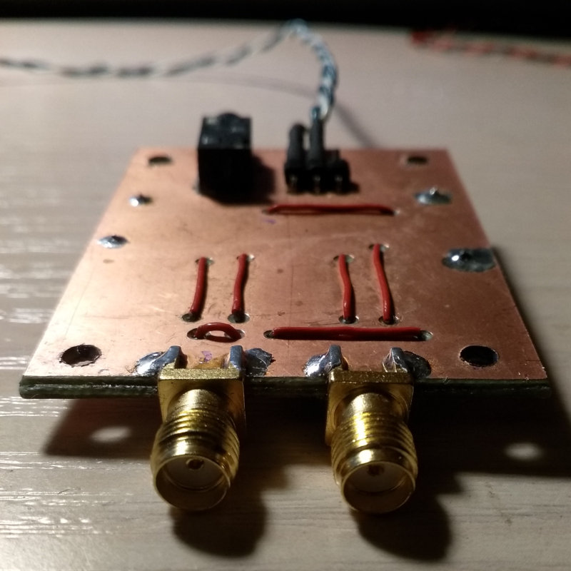
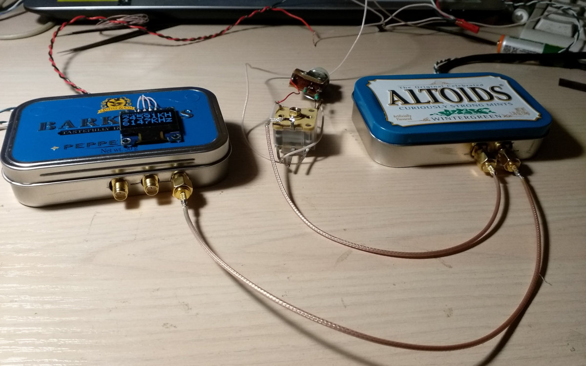
The boards are placed in tin cases that perform the shielding function.
The synthesizer’s encoder is mounted separately – together with the buttons switching between ranges and changing bands.

You can use LM358 instead of NE5532, but the first microchip is preferable because it’s not that noisy. And of course, the most important component of the device is antenna. The best variant is to use a long enough outdoor antenna (preferably, outside of the city). However, a piece of wire stretched across the room would suffice, too. Especially if you connect to it a U-shaped circuit and tune it to maximize the signal.
A magnetic antenna is a good variant, too. Its main advantage is a higher signal/noise ratio, which is especially actual in the city.
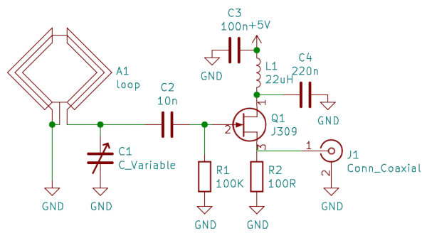
The loop is made of coaxial cable; its diameter is 400 mm; the J309 transistor can be replaced by BF245. The antenna and preamplifier can also be mounted on a prototype board.
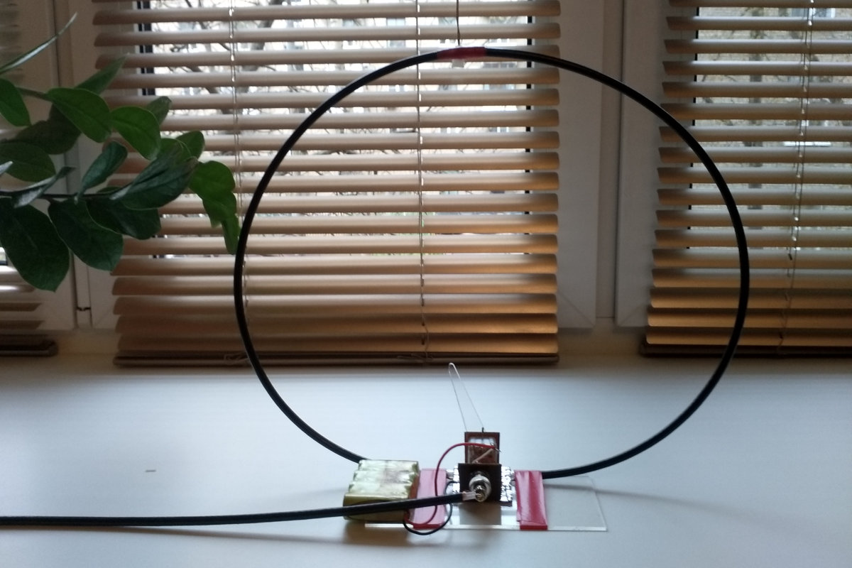
The device has been assembled at home using available parts (damn coronavirus!). It’s pretty compact and works well in the range from 5.8 MHz to 19000 MHz. To expand the range to even lower frequencies, add some capacitance to the variable capacitor.
Key to start!
To test the receiver’s functionality, I connect it to an oscillograph first. I set the frequency to 12 MHz on the synthesizer (3 MHz after the phase shifter), and connect a signal generator (3 MHz sinusoid with the amplitude of 300 μV) instead of the antenna. If the synthesizer is configured correctly, the output beat frequency should be just a few hertz. In other words, I use the generator to calibrate the synthesizer by adjusting the quartz resonator frequency in the firmware. By the way, instead of altering the frequency, I could use the same function to set the deviation in ppm.
si5351_init(SI5351_CRYSTAL_LOAD_10PF, 25005500, 0);When the beat frequency goes through 0, the phase shift between I and Q abruptly changes from 90° to -90°. This indicates that everything is working correctly. Now I can connect the receiver to an audio card. Any card with a stereo line input would fit. In this particular case, I don’t care much about the bandwidth because I can always shift the reference signal.
Software
Plenty of programs for SDR systems are available online, but most of them are designed for RTL-SDR and its highly specialized variants (e.g. HackRF, airspy, etc.). Personally, I prefer SDR# that supports signal capture from the sound card. Thanks to it intuitive interface, SDR# is very popular, and numerous manuals for it can be found on the Internet.
I install and launch the program, set the desired band on the synthesizer, adjust the antenna to the maximum signal, turn on the AM demodulator (the interesting stuff in the short-wave range is mostly AM-modulated) – and voila! The receiver operates very steadily, light years better than regenerative analogues (that are still sometimes assembled by enthusiasts) of a similar complexity. Of course, both the image channel and the reflections can be seen (the latter ones are especially distinct for powerful stations) – but this is a price to pay for the radio link simplicity. You can eliminate reflections by using a low pass filter at the output of the operation amplifier. To suppress the image channel, try balancing the channels, at least by amplitude.
There is also another program for Windows – SDRadio – but it’s minimalist and slightly obsolete.
The situation with Linux is more complicated: gqrx is suitable only for RTL chips and does not support signal capture from the sound card. Therefore, I will use GNU Radio.
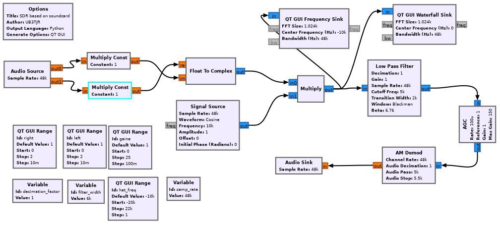
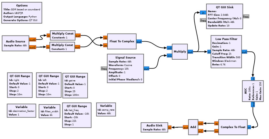
I launch gnuradio-companion and build a simple graph. Using audio as the source, I set in its properties the number of outputs (2) and sample . Any audio card will work with such settings. When the number of audio outputs is set to two, the left and right capture channels are used automatically.
If necessary, you may choose from several audio cards. Then I put the block float that creates one complex value from the two real values and connect the source to its inputs. It also helps to insert a multiplication by a constant between audio andfloat : this allows to balance the channels by amplitude. Finally, I put a low pass filter and specify for it a cutoff frequency: 5 kHz. The filter will provide the required 5-kHz signal bandwidth around the zero point.
GNU Radio has an extremely useful function: you can use variables whose values are specified separately and change them in the interactive mode using the respective interface elements. I connect to the filter output an AM demodulator (that calculates the complex signal module) and Audio . In this particular case, the sample rates of the source and receiver are the same; so, I don’t have to use resampling to match them. A simple AM receiver is ready!
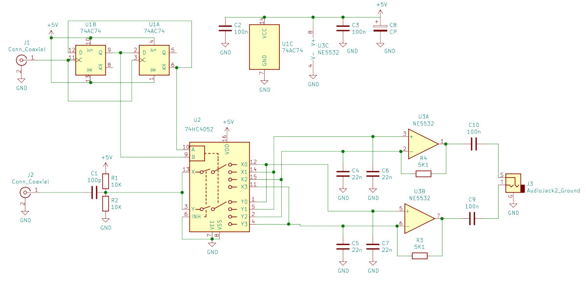
The device receives signals from a radio station at the local oscillator frequency, i.e. in the center of the band transmitted to the audio card. To see the signal spectrum, I add the QT element that draws it. QT should be connected to the output of the float block. Similarly, the QT element is responsible for the ‘waterfall’.
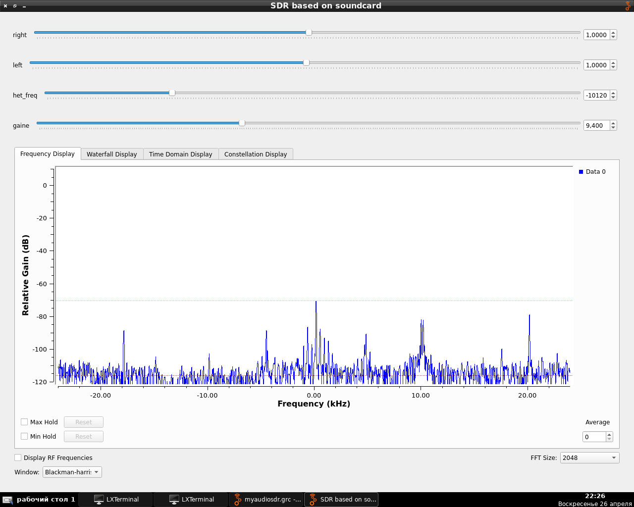
Everything seems to be fine in the receiver, except for the possibility to tune the frequency in the window at the software level. This feature is very useful taking that audio cards often produce artifacts in various sections of the window. For instance, my card produces artifacts at the zero point (+/-100 Hz); apparently, this is because noises generated by the power line interfere with the signal.
It’s not a big deal to enable the software frequency control; all you have to do is add one more multiplication unit between float andLow – but in this case, the signal must be multiplied not by a constant, but by a function (i.e. by the second signal). I use the Signal block as the source of the second signal; its waveform is the cosine; and its frequency must be equal to the frequency I need to shift the signal to.
So, I have effectively added one more frequency converter (a software one) to the receiver. Now I can tweak the Signal frequency to select a portion of the window to be sent to the detector. In other words, I shifted the zero point in my window. The resultant receiver graph is shown on the diagram below:
If you want to listen to amateur radio enthusiasts – no problem, you just need the real part of the signal (or the imaginary part, or their sum – it doesn’t matter in this case) instead of the signal module. This is how an AM receiver can be transformed into a direct-conversion receiver! Don’t forget to adjust the filter bandpass because the device now uses single-sideband modulation (SSB). The best way is to set it somewhere around 1500 Hz.
Radio enthusiasts can be heard at the wavelength of 40 m. The diagram below shows the reception of China Radio International in the AM mode.
Bonus
But what if your laptop has no sound card? Of course, you can buy an external one or a converter for your RTL-SDR – but its cost exceeds the price of an RTL dongle by times. Chinese manufacturers also offer a modified RTL-SDR v3 model that supports direct conversion; its price is not that outrageous – but still too high in comparison with RTL-SDR… Under such circumstances, the only suitable solution is to hack the device!
warning
The manipulations described below may damage your RTL-SDR; in the worst case scenario, they may burn out the USB port and the motherboard. Therefore, perform these operations at your own peril and risk and only if you know exactly what you are doing. I have warned you!
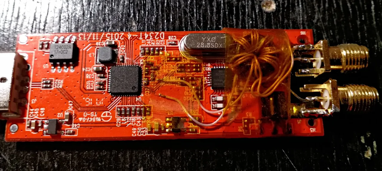
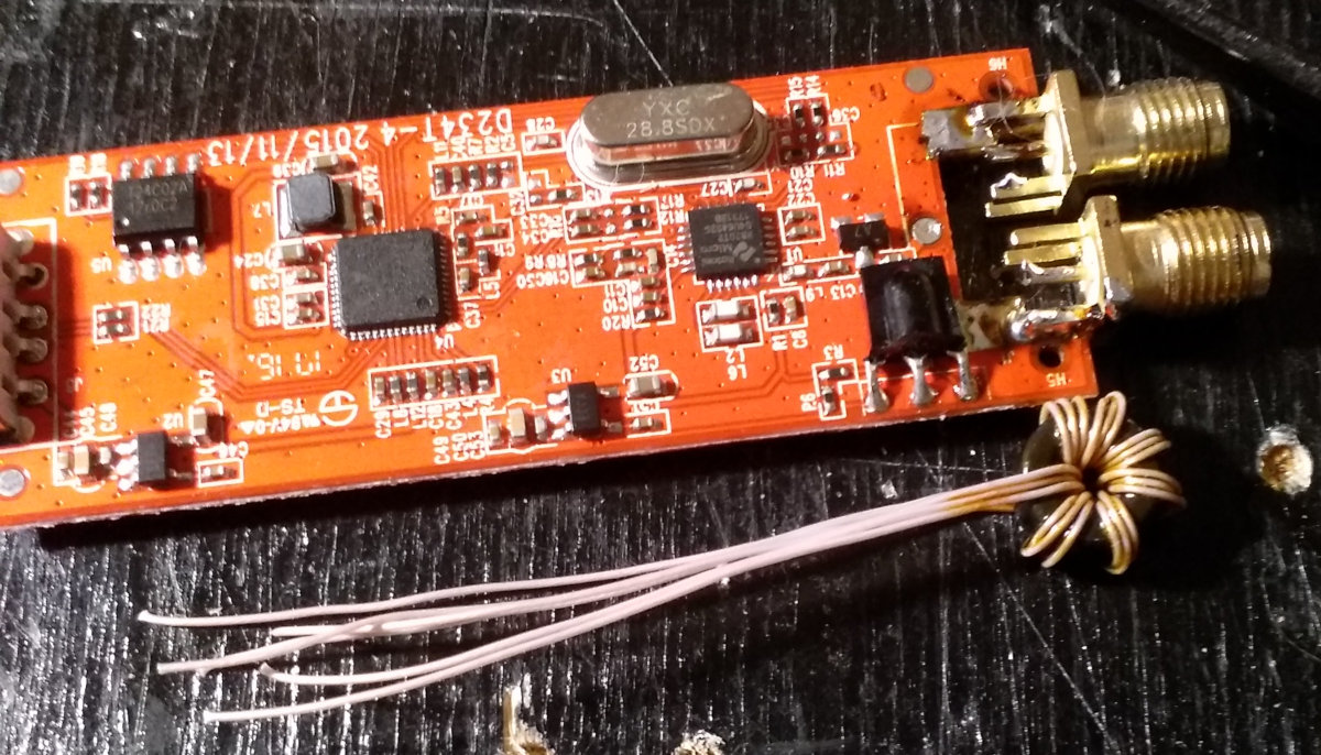
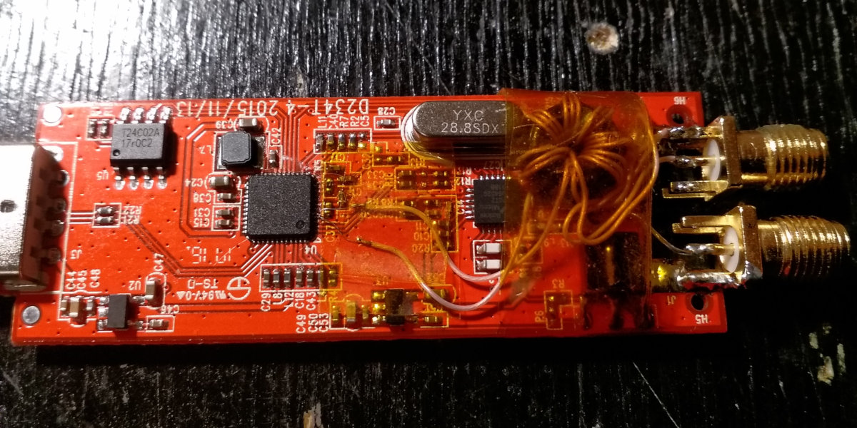
As you are aware, RTL2832U has an analog-to-digital converter (ADC) at its input. Furthermore, according to a datasheet produced by enthusiasts, there are two ADCs and both have differential inputs. The chip can digitize signals up to 30 MHz. All you have to do is transmit a signal to the input (even one input will suffice). In the simplest variant, you can unsolder the frequency converter chip and solder in the antenna. You may even leave the chip in place and just cut the respective tracks.
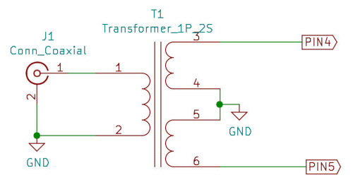
But I suggest a more elegant solution. I assume that you use the RT820 chip as the converter as it’s best suited for this function. The point is that RT820 uses only I input of the RTL2832U microcircuit (pins 1 and 2), while the Q input (pins 4 and 5) remains unused.
I am going to connect to these pins. Furthermore, I can optionally add a transformer; this allows to use the input differential, protects against static electricity, and somewhat matches the resistance. Honestly, I don’t care mach about the latter. By contrast, protection against static electricity is of utmost importance; otherwise, the device may suddenly brick. The transformer is created by coiling three wires folded together on a ferrite ring; it consists of six turns; the windings are phased as shown on the diagram.
If you don’t want to create the transformer manually, use a premade one, for instance, from an ADSL modem. The only problem of this modification is that RTL2832U has a 0.5-mm pitch, and the leads are very short. As a result, I was unable to solder a 30 AWG wire to the contacts. Instead, I soldered a 0.1-mm (38 AWG) wire to them and connected the transformer leads to this wire. To keep this fragile structure together and prevent it from collapsing, I used a thermal tape.
Of course, this modification requires certain technical skills, but I guarantee that it’s 100% feasible (I spent some half an hour on it). I run gqrx with the device parameters rtl=0, and see that everything is working fine. Then I connect a loop antenna and start listening in. The direct_samp=2 parameter indicates that the device must directly digitize the signal received at the Q input. In addition, the device retains its basic functionality: if launched with the standard parameters, it still can receive ultrashort waves.
Of course, such a simple solution has its shortcomings, including interference from FM stations, false signals, and other issues; but still, by its quality, my makeshift device is on par with RTL-SDR v3. In addition, it would be great to equip your radio with an input filter with a cutoff frequency of some 30 MHz and a durable shielded case. Good luck!