How It All Began
It all began with a Kickstarter campaign. Damien George, a developer from England, designed a microcontroller board specifically for Python. The campaign was a hit. Originally, the goal was set at £15,000, but ultimately, it raised six and a half times that amount—£97,803.
What Makes This Board Better?
The project creator highlighted several advantages of their platform compared to Raspberry Pi and Arduino:
- Performance: MP is more powerful compared to the Arduino microcontroller as it uses 32-bit ARM processors like the STM32F405 (168 MHz Cortex-M4, 1 MB flash memory, 192 KB RAM).
- Ease of Use: MicroPython is based on Python but simplified so that commands for controlling sensors and motors can be written in just a few lines.
- No Compiler: Running a program on the MicroPython platform does not require installing additional software on a computer. The board is recognized as a regular USB drive, and you simply need to upload a text file with code and reboot the device for the program to execute immediately. For convenience, you can install a terminal emulator on the PC, allowing you to enter code elements directly on the platform. Using this method, you won’t even need to reboot the board to test the program, as each line will be executed by the microcontroller instantly.
- Cost-effectiveness: Compared to the Raspberry Pi, the PyBoard platform is somewhat cheaper, making it more accessible.
- Open Platform: Like Arduino, PyBoard is an open platform, meaning all its schematics are publicly available. This allows you to design and create a similar board yourself according to your needs.
Does that mean only the official board works?
No. Despite its advantages, the PyBoard (the board from the MicroPython developer) is quite expensive. However, thanks to its open platform, you can already run MicroPython, specially built for many popular boards. Currently, there are versions available for:
- BBC micro:bit — a British development, promoted as the official educational tool for computer science lessons.
- Circuit Playground Express — developed by the well-known company Adafruit. This board includes LEDs, sensors, pins, and buttons and is primarily programmed using Microsoft MakeCode for Adafruit, a block-based (similar to Scratch) code editor.
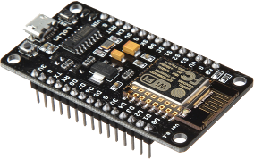
- ESP8266/ESP32 — one of the most popular boards for IoT development. Initially, it could be programmed using Arduino C and Lua. Today, we will attempt to install MicroPython on it.
Getting Ready to Start
Before writing programs, you need to configure the board, install the firmware on it, and set up the necessary software on your computer.
info
All examples were checked and tested on the following hardware:
- NodeMCU ESP8266-12E board
- L293D motor driver
- 0.96″ 128 × 64 I2C display
- Adafruit NeoPixel Ring 16
Flashing the Microcontroller
To flash the board, we’ll need Python. More precisely, it’s not Python itself but the esptool utility, which is distributed via pip. If you have Python installed (the version doesn’t matter), open a terminal (command prompt) and type:
pip install esptool
After installing esptool, you need to do two things. First, download the firmware version for ESP8266 from the official website. Second, determine the board’s address when connected to a computer. The simplest way to do this is to connect it to the computer, open the Arduino IDE, and check the address in the list of ports.
To simplify the instructions, we’ll use / as the board’s address in the example, and the firmware file has been renamed to esp8266. and placed on the desktop.
Open the terminal (command line) and navigate to the desktop:
cd Desktop
Formatting the board’s flash memory:
esptool.py --port /dev/ttyUSB0 erase_flash
If errors occur during formatting, you’ll need to switch to manual flashing mode. Press and hold the reset and flash buttons on the board. Then release the reset button while still holding the flash button, and attempt formatting again.
And upload the firmware to the board:
esptool.py --port /dev/ttyUSB0 --baud 460800 write_flash --flash_size=detect 0 esp8266.bin
Interfacing with the Board
Interaction with the board can occur in several ways:
- via Serial port;
- via web interface.
When connecting via the serial port, the user sees what appears to be a standard Python interpreter in their terminal (command line).
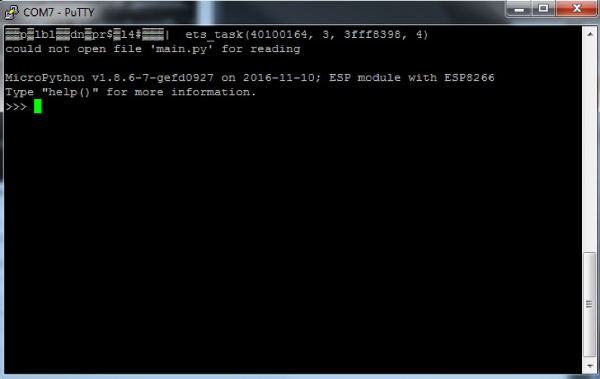
There are various programs available for Serial connections. For Windows, you can use PuTTY or TeraTerm. For Linux, options include picocom or minicom. As a cross-platform solution, you can use the serial monitor in Arduino IDE. The key is to correctly identify the port and set the baud rate to 115200.
picocom /dev/ttyUSB0 -b115200
Additionally, several programs have been created and uploaded to GitHub to facilitate development, such as EsPy. It includes a Python file editor with syntax highlighting and a file manager that allows downloading and uploading files to an ESP, alongside a Serial port feature.
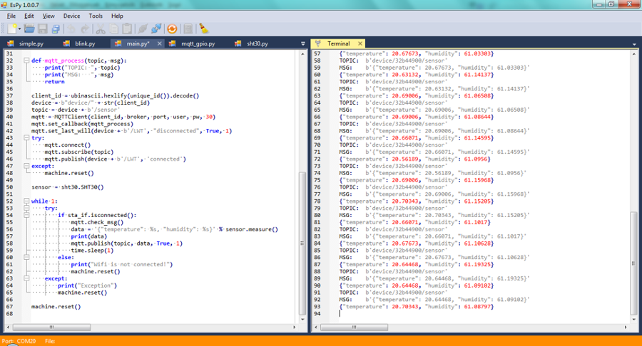
However, all the methods listed are only effective when we have the opportunity to directly connect to the device using a cable. But if the board is integrated into a device, dismantling it just to update the program is somewhat inefficient. Probably for such scenarios, WebREPL was created. It allows interaction with the board via a browser from any device in the same local network if the board lacks a static IP, and from any computer if such an IP is available. Let’s set up WebREPL. To do this, after connecting to the board, you should type
import webrepl_setup
A message will appear indicating the status of WebREPL’s auto-start, along with a question asking whether to enable or disable its auto-start feature.
WebREPL daemon auto-start status: enabled
Would you like to (E)nable or (D)isable it running on boot?
(Empty line to quit)
>
After entering ‘q’, a prompt appears to set a password:
To enable WebREPL, you must set password for it
New password (4-9 chars):
Enter it, then confirm. Now, after restarting, we will be able to connect to the board via Wi-Fi.
Since we haven’t configured the board to connect to a Wi-Fi network, it operates as an access point. The Wi-Fi network name is MicroPython-******, where the asterisks replace part of the MAC address. Connect to it using the password micropythoN.
Open WebREPL and click on “Connect.” After entering the password, you’ll access the same interface as with a direct connection. Additionally, WebREPL offers an interface for uploading files to the board and downloading files to your computer.

info
Among the files uploaded to the board, there are standard ones:
-
boot.— a script that runs first when the board is powered on. It usually contains functions for initializing modules, connecting to Wi-Fi, and launching WebREPL.py -
main.— the main script that runs immediately after boot.py is executed. It contains the core logic of the program.py
Kicking Off Development
Hello world
It’s a tradition for the first program written in a new programming language to display “Hello, World.” Let’s stick with tradition and output this message using Morse code.
import machine
import time
pin = machine.Pin(2,machine.Pin.OUT)
def dot_show():
    pin.off()
    time.sleep(1)
    pin.on()
def dash_show():
    pin.off()
    time.sleep(2)
    pin.on()
Hello_world = '**** * *-** *-** ---    *-- --- *-* *-** -**'
for i in Hello_world:
    if i=="*":
        dot_show()
    elif i=='-':
        dash_show()
    else:
        time.sleep(3)
    time.sleep(0.5)
So, what is happening here? Firstly, libraries are imported: the standard Python library time and the specialized library machine. The machine library is responsible for interfacing with GPIO (General Purpose Input/Output). The built-in LED is located on the second pin. We connect it and specify that it operates in output mode. If we had a sensor connected, we would set it to work in input mode.
The following two functions are responsible for turning the LED on and off for a specific interval of time. You might be curious why I first turn off the LED and then turn it on. I’m also quite curious why the signal for this LED is inverted… Let’s attribute that to the conscience of the Chinese manufacturers. In actuality, the pin. command turns the LED on, while pin. turns it off.
The next step is straightforward: we store our Morse code string in the variable Hello_world. Then, as we iterate through it, we call the corresponding functions.
A World of Color
One of the standard libraries included with MicroPython is the NeoPixel library. It is used for working with RGB LEDs produced by Adafruit. To connect, three pins are required: one for ground, one for power (3.3V), and another for control. I use GPIO4, but you can choose any pin you prefer.
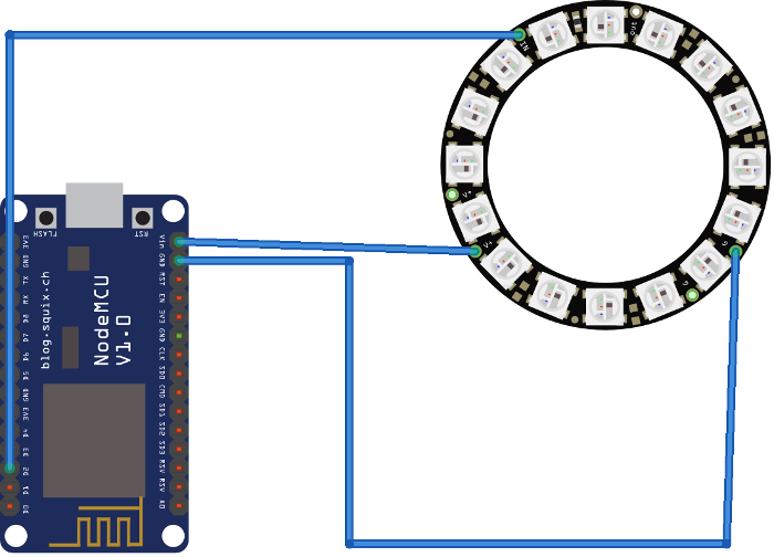
import machine, neopixel,time,urandom
my_neopixel_ring = neopixel.NeoPixel(machine.Pin(4), 16)
def color_all(neopixel_ring, color):
    for i in range(neopixel_ring.n):
        neopixel_ring[i] = color
    neopixel_ring.write()
def color_all_slow(neopixel_ring, color):
    for i in range(neopixel_ring.n):
        neopixel_ring[i] = color
        neopixel_ring.write()
        time.sleep(0.5)
def color_random(neopixel_ring):
    for i in range(neopixel_ring.n):
        color =  (urandom.getrandbits(8),urandom.getrandbits(8),urandom.getrandbits(8))
        neopixel_ring[i] = color
    neopixel_ring.write()
def disable(neopixel_ring):
    for i in range(neopixel_ring.n):
        neopixel_ring[i] = (0,0,0)
    neopixel_ring.write()
def show(neopixel_ring):
    RAINBOW_COLORS = [(255,0,0),(255, 128, 0),(255,255,0),(0,255,0),(0,255,255),(0,0,255), (255,0,255)]
    for i in RAINBOW_COLORS:
        color_all(neopixel_ring,i)
        time.sleep(0.5)
    time.sleep(5)
    disable(neopixel_ring)
    for i in RAINBOW_COLORS:
        color_all_slow(neopixel_ring,i)
        time.sleep(0.5)
    for i in range(100):
        color_random(neopixel_ring)
        time.sleep(0.5)
    disable(neopixel_ring)
Wow, there’s a lot to cover here! Let’s start with the connection. To create a NeoPixel object, you need to specify two parameters: the pin and the number of LEDs. NeoPixels are addressable LEDs, which means you can connect multiple modules in sequence. Essentially, it’s an array where each element holds a tuple in a specific format (RGB).
The color_all function lights up all LEDs in a single color simultaneously, creating an effect that appears “instantaneous” to an observer. In contrast, the color_all_slow function turns on each LED one by one with a half-second delay. This difference is determined by when the write( function is called, as it is responsible for “revealing” the color.
The function color_random colors all the LEDs in different random colors. This is where the difference from the Python version running on a computer becomes noticeable. How would we generate a random tuple on a computer:
import random
color = (random.randrage(256),random.randrage(256),random.randrage(256))
Here, there is no random module, but there is urandom. Using the getrandbits function, you can obtain a random set of bits of a specified length, which means a random number ranging from zero to a power of two. In this case, up to eight.
To turn off the LED, you need to set its color to (0,0,0). But wait, what about brightness? When color is specified using RGB, there is usually a parameter called brightness (or transparency). Here, it is controlled using simple mathematics:
- (255,255,255) — Maximum brightness white;
- (128,128,128) — 50% brightness white;
- (64,64,64) — 25% brightness white.
The show function is a simple demonstration function that illustrates how the previously discussed functions operate.
Display: Drawing, Writing, and Calligraphy
Often, we don’t feel like accessing the device just to check some data. So, we need to display it somewhere, like on a screen. 🙂
from ssd1306 import SSD1306_I2C
import machine
from writer import Writer
import freesans20
import time
WIDTH = const(128)
HEIGHT = const(64)
pscl = machine.Pin(4, machine.Pin.OUT)
psda = machine.Pin(5, machine.Pin.OUT)
i2c = machine.I2C(scl=pscl, sda=psda)
ssd = SSD1306_I2C(WIDTH, HEIGHT, i2c, 0x3c)
ssd.fill(1)
ssd.show()
time.sleep(0.5)
ssd.fill(0)
ssd.show()
ssd.line(40, 0, 40, HEIGHT, 1)
square_side = 40
ssd.fill_rect(0, 0, square_side, square_side, 1)
ssd.text('Hello', 50, 10)
wri2 = Writer(ssd, freesans20, verbose=False)
Writer.set_clip(True, True)
Writer.set_textpos(32, 64)
wri2.printstring('][akep\n')
ssd.show()
To work with the monitor, you’ll need the ssd1306 library, which can be downloaded from GitHub. For I2C connection, we require two pins, using GPIO4 as scl and GPIO5 as sda. Initialize the I2C connection. To verify after initializing the i2c variable, you can call the i2c. function. If everything is connected correctly, the result will be a list like [, which indicates the I2C port number. If you see an empty list, there is a problem with the connection. What can you do with the screen?
- Fill with a single color: white —
ssd.or black —fill( 1) ssd..fill( 0) - Refresh the screen display —
ssd..show( ) - Draw a line from (x0, y0) to (x1, y1) with thickness t —
ssd..line( x0, y0, x1, y1, t) - Draw a pixel at specified coordinates with a given color —
ssd..pixel( x, y, c) - Draw a rectangle given the starting point, side lengths, and color —
ssd..fill_rect( x0, y0, length, width, color) - Write text using the default font —
ssd..text( '', x0, y0)
The standard font has its drawbacks, so a method for creating and using custom fonts is available on GitHub. To do this, you need to create your own font using font-to-py.py, upload the generated font and the Writer module to your device, and utilize it as demonstrated in the example.
Setting Up Wi-Fi and Controlling via a Website
Indeed, constantly connecting to the board’s local network can be inconvenient. However, you can configure the board to connect to an existing Wi-Fi network.
import network
sta_if = network.WLAN(network.STA_IF)
sta_if.active(True)
sta_if.connect('<your ESSID>', '<your password>')
sta_if.isconnected() ## True
sta_if.ifconfig() ##('192.168.0.2', '255.255.255.0', '192.168.0.1', '8.8.8.8')
This section demonstrates how to connect to a specified Wi-Fi network by executing a series of commands. However, this process can be quite monotonous. The official guide suggests adding the following function to the boot.py file:
def do_connect():
    import network
    sta_if = network.WLAN(network.STA_IF)
    if not sta_if.isconnected():
        print('connecting to network...')
        sta_if.active(True)
        sta_if.connect('<essid>', '<password>')
        while not sta_if.isconnected():
            pass
    print('network config:', sta_if.ifconfig())
Great. We’ve connected our board to the internet. Let’s try controlling the LED using a basic website. We won’t need any modules like Flask or Django. Just socket. Pure and simple.
import socket
import machine
html = """<!DOCTYPE html>
<html>
<head> <title> ESP8266 Controller </title> </head>
<form>
<H1>ESP8266 Controller</H1>
<button name="LED" value="ON" type="submit">ON</button><br>
<button name="LED" value="OFF" type="submit">OFF</button>
</form>
</html>
"""
pin = machine.Pin(2, machine.Pin.OUT)
s = socket.socket(socket.AF_INET, socket.SOCK_STREAM)
s.bind(('', 80))
s.listen(5)
while True:
    conn, addr = s.accept()
    print("Connected with " + str(addr))
    request = conn.recv(1024)
    request = str(request)
    LEDON = request.find('/?LED=ON')
    LEDOFF = request.find('/?LED=OFF')
    if LEDON == 6:
        print('TURN LED0 ON')
        pin.off()
    if LEDOFF == 6:
        print('TURN LED0 OFF')
        pin.on()
    response = html
    conn.send(response)
    conn.close()
At the beginning, the HTML code of the page is provided. There are two buttons—one for turning on and the other for turning off. Essentially, they just create and send POST requests to the server.
After describing the site, we reconnect the built-in LED and then create a server. The server’s task is to intercept requests and process them if they contain commands to turn the LED on or off.
Motor Control
I think almost everyone has had, has, or will have a remote-controlled car at some point. (At this point, those born in the early eighties or earlier might tear up, as the pinnacle of their dreams was a non-remote-controlled walking lunar rover. 😉 — Ed. note.) Many people start their journey into DIY by building such a toy. It’s such a popular activity that complete kits have long been available, featuring a wheeled platform with mounts for various boards. Let’s try to create a car controlled via WebREPL.
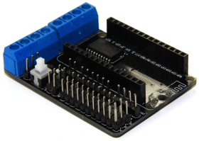
from machine import Pin, PWM
pin1 = Pin(5, Pin.OUT)  # D1
pin2 = Pin(4, Pin.OUT)  # D2
pin3 = Pin(0, Pin.OUT)  # D3
pin4 = Pin(2, Pin.OUT)  # D4
BIN1 = PWM(pin1, freq=750)
BIN2 = PWM(pin3, freq=750)
AIN1 = PWM(pin2, freq=750)
AIN2 = PWM(pin4, freq=750)
speed = 700
def stop_all():
    for each in (BIN1, BIN2, AIN1, AIN2):
        each.duty(0)
def B(tmp1,tmp2):
    BIN1.duty(tmp1)
    BIN2.duty(tmp2)
def A(tmp1,tmp2):
    AIN1.duty(tmp1)
    AIN2.duty(tmp2)
def forward():
    B(speed,0)
    A(speed,speed)
def backward():
    B(speed,speed)
    A(speed,0)
def left():
    B(speed,0)
    A(speed,0)
def right():
    B(speed,speed)
    A(speed,speed)
commands = {'w':forward,'s':backward,'a':left,'d':right,'s':stop_all}
while True:
    a = input().lower()
    try:
        commands[a]()
    except:
        pass
An interesting feature of this code is that we first connect to the pins and then establish a PWM connection to the motors using these pins.
The Internet of Things
Things got a bit awkward… The ESP8266 is marketed as a development board for IoT, and we haven’t done anything with it yet. One of the fundamental concepts of IoT is the MQTT protocol. To save time setting up our own MQTT server, we’ll use the Adafruit IO platform. The library for working with this protocol is already included in the MicroPython build and is called umqtt.
Before diving into programming, you need to set up Adafruit IO. Start by registering an account, then create a new feed and name it enablefield. Next, create a new Dashboard and add a toggle switch to it, specifying the name of the feed we created. To connect, you will need your account name and the Active Key.
import network
from umqtt.simple import MQTTClient
import machine
pin = machine.Pin(2, machine.Pin.OUT)
def sub_cb(topic, msg):
   print(msg)
   if msg == b'ON':
      pin.off()
   elif msg == b'OFF':
      pin.on()
sta_if = network.WLAN(network.STA_IF)
sta_if.active(True)
sta_if.connect('<SSID>', '<PASSWORD>')
client = MQTTClient("my_device", "io.adafruit.com",user="<USER_LOGIN>", password="<API-KEY>", port=1883)
client.set_callback(sub_cb)
client.connect()
client.subscribe(topic="<USER_LOGIN>/feeds/<FEEDNAME>")
while True:
    client.wait_msg()
To work with an external MQTT server, you need to connect to a Wi-Fi network with internet access. The function sub_cb( is responsible for handling incoming messages to a specified topic. After connecting to Wi-Fi, a connection to the MQTT server is established. The topics to which the client is subscribed are defined, and an infinite loop begins to wait for messages in the topic.
Conclusion
MicroPython is a relatively new project, but it has quickly gained popularity, even making it onto the list of 30 Amazing Python Projects for the Past Year (v.2018). I believe this is just the beginning, as there are already numerous projects on GitHub written in MicroPython. Additionally, Adafruit has developed its own educational version called CircuitPython.
