

Glossary
- AP (access point) — an access point.
- BSSID (basic service set identifier) — usually the AP’s MAC address.
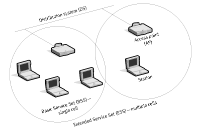
- BSS (basic service set) — a set of stations synchronized to communicate over 802.11 (a single “cell”).
- DA (destination address) — the destination MAC address.
- DS (distribution system) — the system that interconnects BSSs and the wired LAN.
- ESS (extended service set) — multiple BSSs interconnected via the DS and presented as a single logical network (typically sharing the same SSID).
- MPDU (MAC protocol data unit) — an 802.11 frame.
- MSDU (MAC service data unit) — the payload delivered to the MAC, typically an LLC PDU carrying an IP packet.
- PLCP (physical layer convergence procedure) — a PHY sublayer that prepares a MAC frame for transmission over the physical medium.
- PSDU (PLCP service data unit) — essentially the same bits as an MPDU, but from the PHY’s perspective (bottom-up) rather than the MAC’s (top-down).
- SA (source address) — the sender’s MAC address.
- STA (station) — any device that supports 802.11, e.g., a smartphone, laptop, or Raspberry Pi.
Technical Background
It’s no secret that the STM32Fxxx microcontroller family dominates the field today (the letters and digits in the xxx position indicate the device class, ranging from ultra‑low‑power to high‑performance). But a couple of years ago a “wonder chip” arrived: the ESP32—the big brother of the wildly popular ESP8266 Wi‑Fi SoC.
Originally, the documentation for this chip was extremely sparse, but that has changed dramatically. There’s an excellent user guide with step-by-step instructions for everything—from setting up the SDK and toolchain for this microcontroller to detailed coverage of its peripherals. It’s complemented by a wealth of examples on GitHub. In addition, there’s a very good blog that clearly explains how to work with various peripherals.
Credit where it’s due: Espressif documents how to install the toolchain for popular platforms:
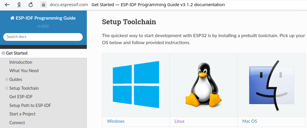
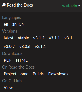
All documentation is available in two formats:
- The latest branch, which includes all the newest, cutting-edge SDK features. However, they haven’t been thoroughly tested yet.
- The stable branch (at the time of writing, stable was 3.1.2), which doesn’t include every new feature but is recommended for production use.
Right, I forgot to mention their excellent forum, where you can discuss anything related to the ESP32. It seems Espressif’s support is pretty quick to respond.
We already mentioned this chip in one of our articles, so here I’ll just briefly list the key specs:
- 32-bit MCU based on Xtensa LX6 single-/dual-core CPU(s), capable of operating across a wide frequency range;
-
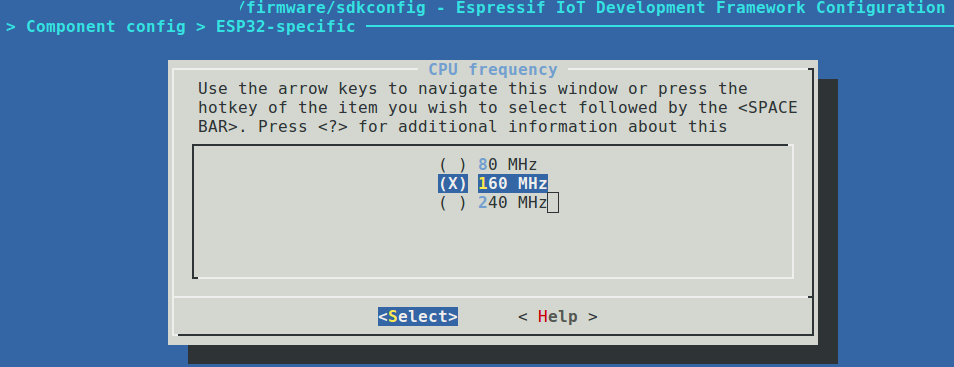
- 520 KB SRAM;
- A standard peripheral set including UART/SPI/I2C, SD card, Ethernet MAC (RMII), and CAN 2.0;
- Wi‑Fi (802.11b/g/n);
- Bluetooth v4.2 (BR/EDR and BLE).
Assembly fans get a real treat: the manufacturer includes an Ultra Low Power (ULP) coprocessor that’s programmable in assembly and draws as little as 150 µA in deep-sleep—ideal for those chasing maximum battery life. Also, be sure to check the datasheet for details; it’s packed with useful information.
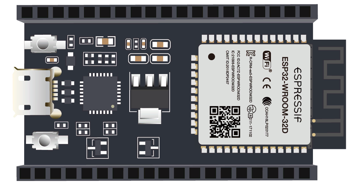
By the way, if by now I’ve made you really want this chip and you’ve already started trying to recall your AliExpress password and the address of your nearest Russian Post office, hold up. 🙂 Surprisingly, you can buy various ESP32 variants locally, and sometimes it’s cheaper and faster than ordering from China. For example, here’s a two‑centimeter module with support for an external antenna:
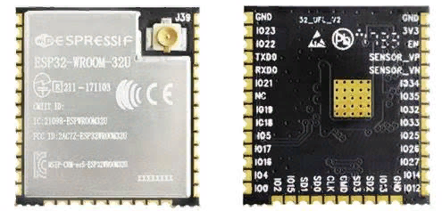
You can buy it here or here for about four dollars.
Wi‑Fi Theory (yeah, there’s no way around it)
I’m going to take on a very ambitious mission: to boil down a three-thousand-page standard into a few sentences. 🙂 I think I can pull it off—no turning back now, right?
You probably already know that “Wi‑Fi” is just a friendly name for a whole family of 802.11 standards. Here are just a few of them:
- 900 MHz — 802.11ah;
- 2.4 GHz — 802.11b, 802.11g, 802.11n, 802.11ax;
- 3.6 GHz — 802.11y;
- 4.9 GHz — 802.11j;
- 5 GHz — 802.11a, 802.11n, 802.11ac, 802.11ax;
- 5.9 GHz — 802.11p;
- 45 GHz — 802.11aj;
- 60 GHz — 802.11aj, 802.11ay.
Since this project calls for understanding the details—not just firing up some magic tool on a wonderful piece of hardware—let’s dive deeper into 802.11. According to IEEE 802.11-2012, the MAC frame has the following structure:
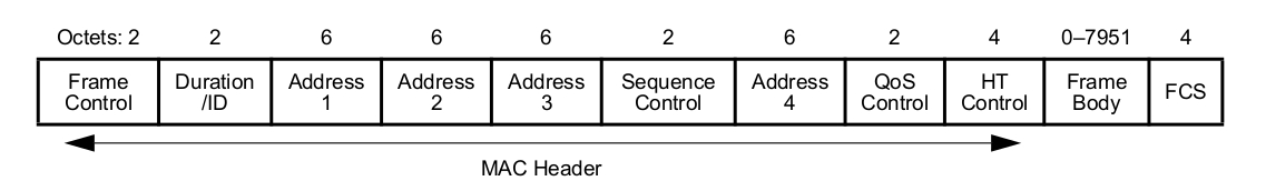
Now let’s go through each field to understand what it does.
Frame Control
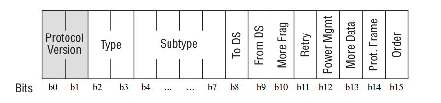
- Protocol Version — per the relevant standard, the value is always 0. All other values are reserved.
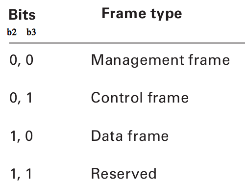
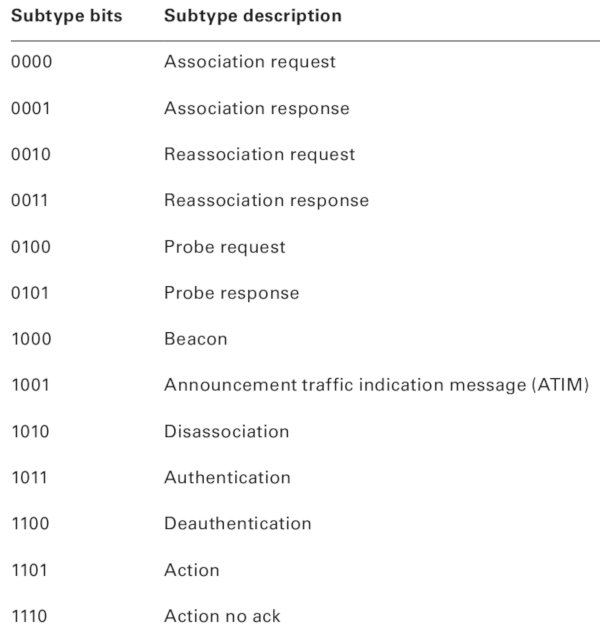
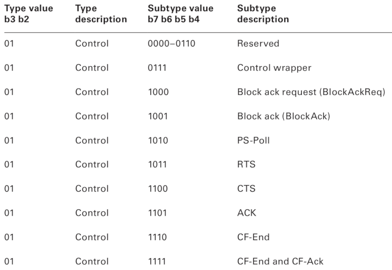
- Type and Subtype — indicate the frame’s type and subtype. There are three frame types: Management, Data, and Control, each with multiple subtypes.
We’ll cover the types of management, control, and data frames once we finish going through the 802.11 MAC header.
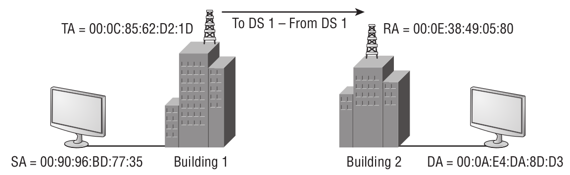
- To DS, From DS — treat these together: they determine how to interpret Address 1…Address 4 in the frame header. See the table below.
- Source Address (SA) — MAC address of the original sender (your phone or laptop you’re using to get online).
- Destination Address (DA) — MAC address of the final destination (the server you opened to read this article).
- Transmitter Address (TA) — MAC address of the device transmitting the 802.11 frame (the access point you’re connected through).
- Receiver Address (RA) — MAC address of the device receiving the 802.11 frame.
- Basic Service Set Identifier (BSSID) — L2 identifier of the basic service set (BSS).
The fourth case (when both bits are set to 1) is illustrated by the following diagram:
- More Frag is set to 1 in all Data and Management frames to indicate that additional fragments of the current MSDU or MMPDU follow.
- Retry is set to 1 when the frame is a retransmission of an earlier frame.
- Power Mgmt is set to 1 when the client signals it is in Power Save mode; the AP should buffer frames destined for that client.
- More Data is set to 1 by the AP to tell a STA in Power Save mode that more frames are queued for it and it should not go back to sleep yet.
- Protected Frame: as the name suggests, a 1 in this bit indicates the frame is protected (encrypted).
- Order is set in any non‑QoS Data frame when the application requires strictly ordered delivery.
Duration/ID
A somewhat opaque field, because the meaning of these 16 bits depends heavily on the frame type—Data, Control, or Management. For example, in a Control PS-Poll frame (discussed later), it carries the AID. It can also indicate the time, in microseconds, required to transmit the next fragment of a Data frame.
Another Interesting Piece of Hardware from Cypress
The CYW43907 is appealing because it supports dual band (2.4/5 GHz) and has onboard USB 2.0. Most interesting for us, it appears to support promiscuous (monitor) mode. I say “appears” because I couldn’t find a definitive mention in the documentation or the programming user guide, but if you look here, that forum thread says that starting with SDK 2.4.1 there’s a function called wiced_wifi_enable_monitor_mode(), which lets you listen to the air and capture 802.11 frames.
Sequence Control
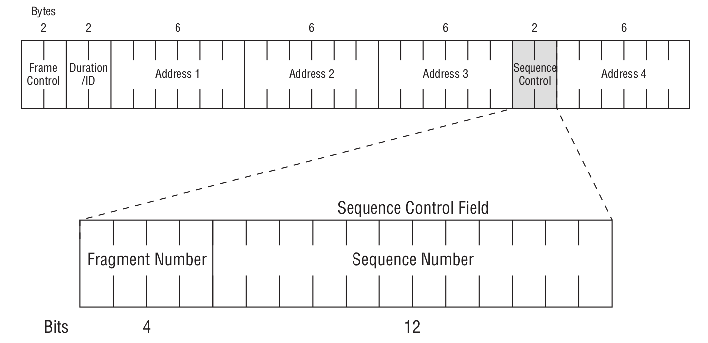
As we can see from the figure above, it is further divided into a Fragment Number and a Sequence Number. The Sequence Number indicates the order within MSDU, A‑MSDU, or MMPDU frames. The Fragment Number indicates the index of each fragment within MSDU or MMPDU frames. To better understand how the Sequence Number works together with the Fragment Number, see the figure below.
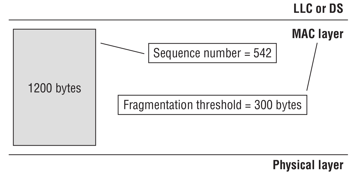
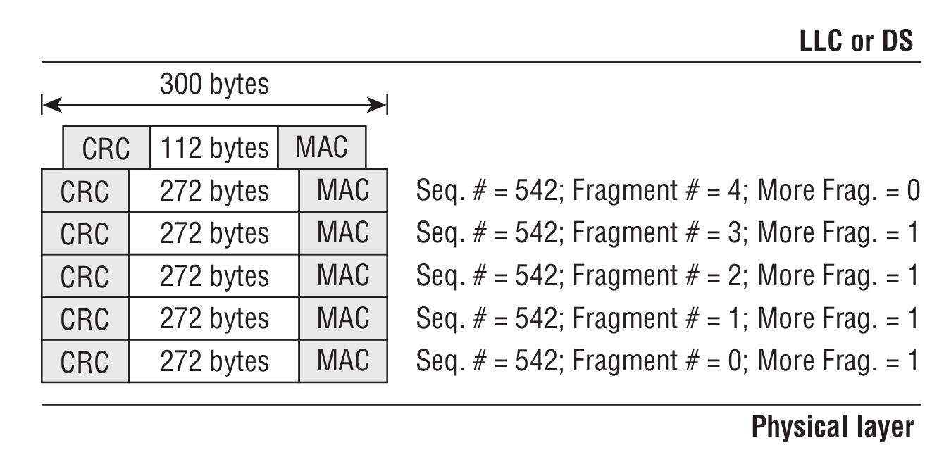
We need to send 1,200 bytes of data, but the access point is configured so that each transmitted frame is 300 bytes. Sending a single 1,200-byte message would look like this.
QoS Control
The sixteenth field, which is responsible for Quality of Service (QoS) in a data frame.
HT Control
The last field is HT Control, which may appear in the MAC header of an 802.11 frame. The 802.11n standard extends the data header with a four-byte field. It is present only in QoS Data and Management frames, and its presence is indicated by the Order bit in the Frame Control field.
Body
Upper-layer protocols are encapsulated in the Body field.
802.11 Frame Subtypes
As promised, let’s take a closer look at the subtypes of Control, Management, and Data frames.
Management frame
As the name suggests, this frame type serves as the “skeleton” for building a wireless network.
Beacon Frame
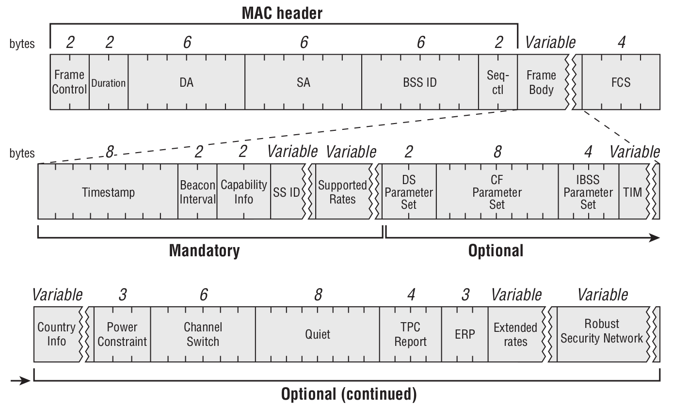
Wi‑Fi is typically used with an access point (or in IBSS mode—when devices try to form an ad‑hoc network, i.e., when you want to connect your smartphone directly to your laptop without an AP). The access point periodically sends beacons to announce its presence and provide necessary information (SSID, channel, timestamps for time synchronization, supported data rates, QoS capabilities, and so on) to all devices within range.
Probe Request Frame
This is what happens when you turn on Wi‑Fi on your smartphone to connect to a wireless network. It’s usually sent to the broadcast destination address (ff:).
Probe Response Frame
Upon receiving a Probe Request, an access point or a client device operating in IBSS mode sends this frame. Its format closely resembles a Beacon frame and includes the information needed for association and connection establishment.
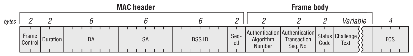
Authentication Frame
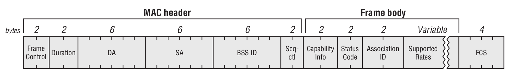
Association request
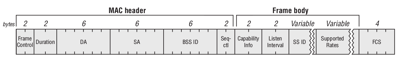
It contains information about the device’s wireless NIC (e.g., supported data rates) and the SSID of the WLAN the device wants to join. Upon receiving the association request, the access point decides whether to accept the association; if approved, it allocates memory and assigns an Association Identifier (AID) for that wireless NIC (the user’s device).
Association response
Disassociation Frame
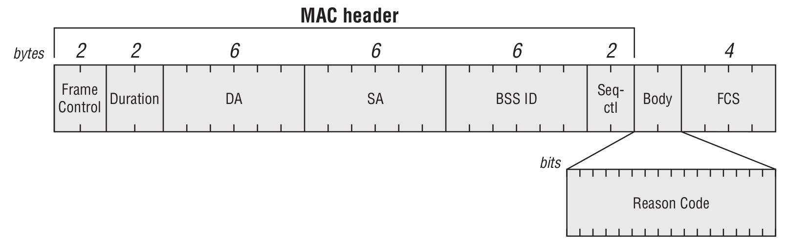
The DA field can be either the specific address of the client to disconnect, or a broadcast address if the AP decides to drop all associations. Note that a disassociated STA remains in the authenticated state with the access point. This frame is used when the AP or the client needs to re-evaluate or renegotiate link parameters.
Deauthentication Frame
The format is similar to a Disassociation frame. This frame type is used to tear down all communication between a client and an access point. Deauthentication and Disassociation frames are identified by the Subtype field. The ESP8266 also has an attack implementation known as Deauther. If you’re interested, check out ESP8266 Deauther 2.0 or Wi-PWN.
Reassociation Request Frame
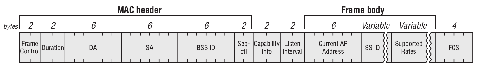
This frame is sent exclusively by the client to the access point. This happens when a station (STA) is already associated with an AP in an ESS and wants to reassociate with another AP within the same ESS (Extended Service Set).
Control frame
One of the key features of these frames (and what sets them apart from Management and Data frames) is that they have no Body field. The main types of Control frames are shown below:
RTS/CTS Frames
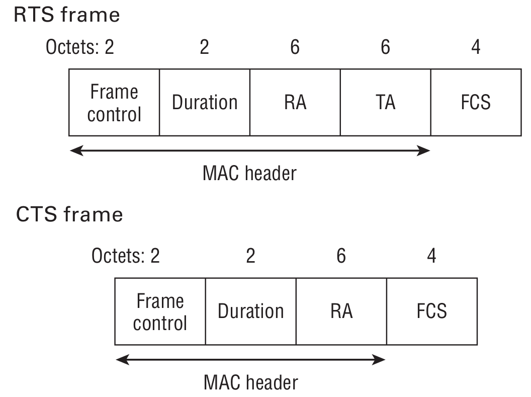
They expand to request to send (RTS) and clear to send (CTS), respectively. In general, they help coordinate communication between a STA and an AP. Imagine the access point is next to a structural wall: you’re online on your smartphone, and your friend is at the other end of the apartment on a laptop. Both devices can see the AP just fine, but they can’t hear each other over the air, so to let both of you browse without collisions, your devices will use these frames.
Client devices send an RTS (Request to Send) frame to another device as the first step in a two-stage process required before transmitting a data frame. In response, a CTS (Clear to Send) frame is returned, indicating how long all other devices on the network should remain silent.
Acknowledgement Frame
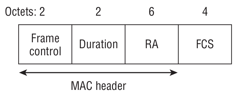
We don’t live in a perfect world—there’s plenty of interference, especially when it comes to radio transmission. This frame is generated by the receiver after it checks the received Data frame for errors.
Block Acknowledgement Request
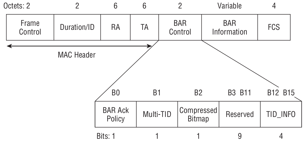
The core idea is to speed up data transfer by acknowledging multiple received data frames at once rather than each one individually. But before you use this mechanism, you need to make sure the receiver supports it.
- RA — receiver’s MAC address.
- TA — transmitter’s MAC address (of the BlockAck Request frame).
Block Acknowledgement
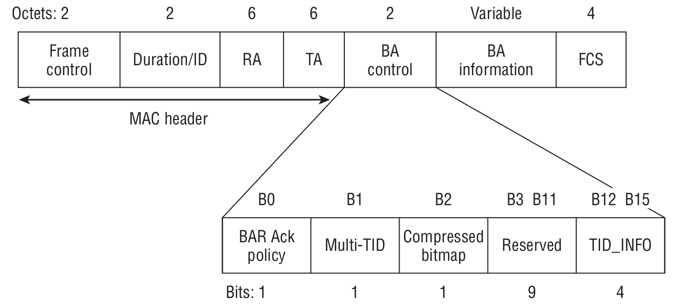
The acknowledgment frame itself, generated upon successful receipt of multiple QoS Data frames, rather than acknowledging each one individually.
- RA — the MAC address of the station that requests the Block Ack frame.
- TA — the MAC address of the station that transmits the Block Ack.
PS-Poll
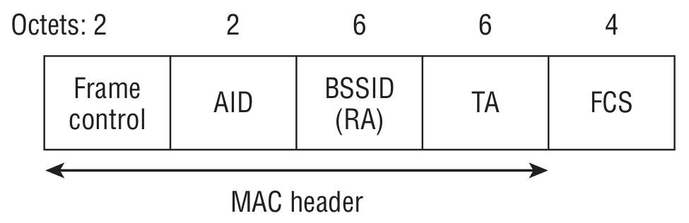
When the client device wakes from sleep and receives a Beacon, it checks for its AID in the TIM (which effectively means the access point has buffered data for it). In that case, the STA sends a PS-Poll to the access point, signaling that it’s ready to receive the queued data.
- BSSID (RA) — the MAC address of the access point the client is associated with.
- TA — the MAC address of the client that generated the PS-Poll.
Control Wrapper
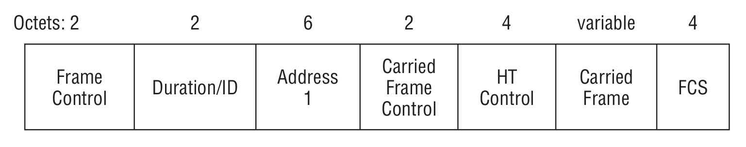
Defined in the 802.11n standard, which gives a rather “interesting” interpretation of this frame: it can be used with any other control frame (except the Control Wrapper frame) in conjunction with the HT Control field.
Contention Free
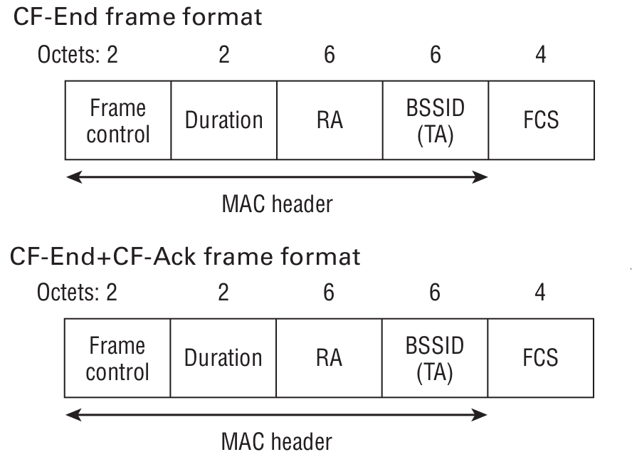
Both frames are used to signal that the CFP (contention-free period) has ended. In the second case, an acknowledgment (ACK) frame is required.
Data Frame
If you recall how this frame is described under Control frames, it shouldn’t surprise you that there are 15 different types of Data frames.
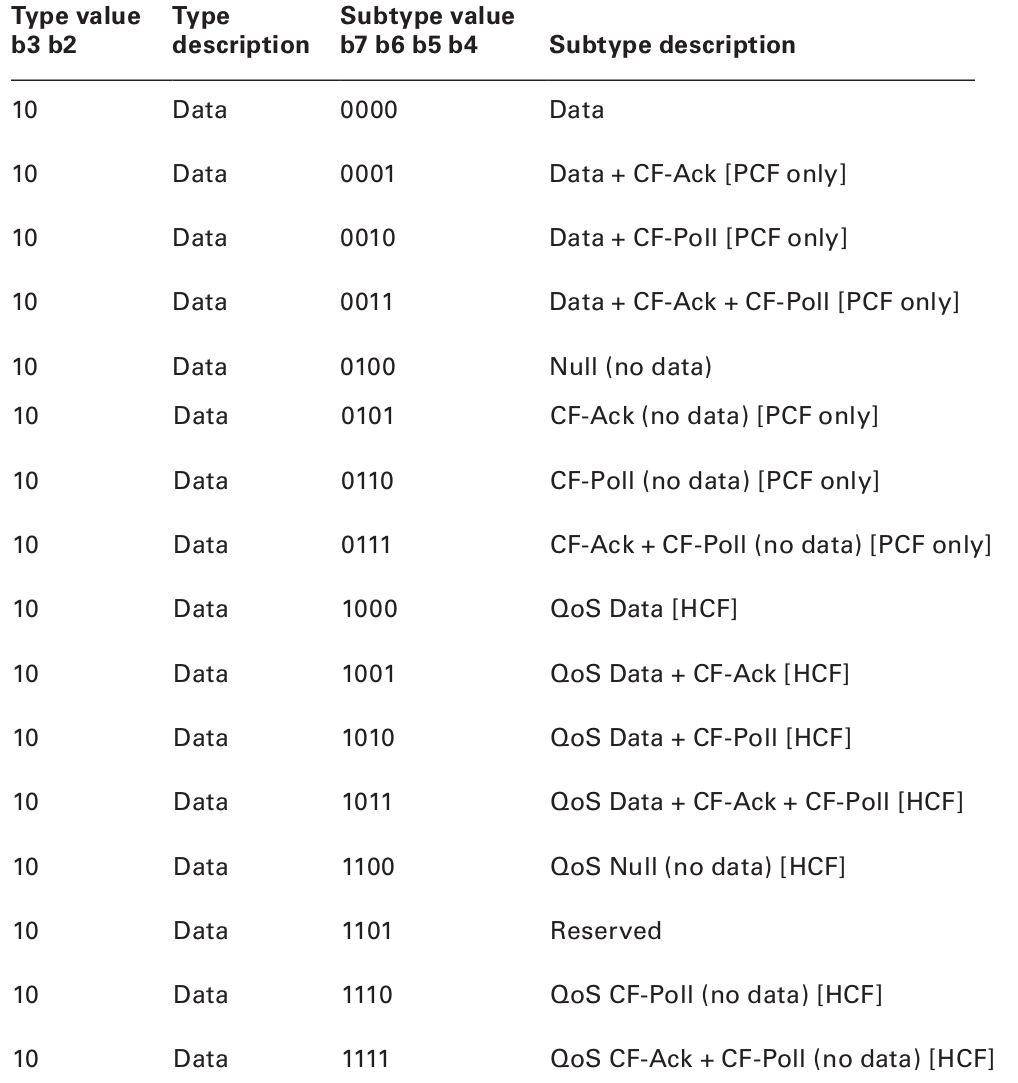
A careful reader will notice that data frames can be split into two broad categories: those that carry payload data and those that don’t. That begs the question: why have a data frame with no data? The answer may surprise you: sometimes you need to send housekeeping information to the access point or another station. Nodes sometimes use null data frames to enter or exit power-save mode.
By the way, it’s worth noting that frames can be fragmented.
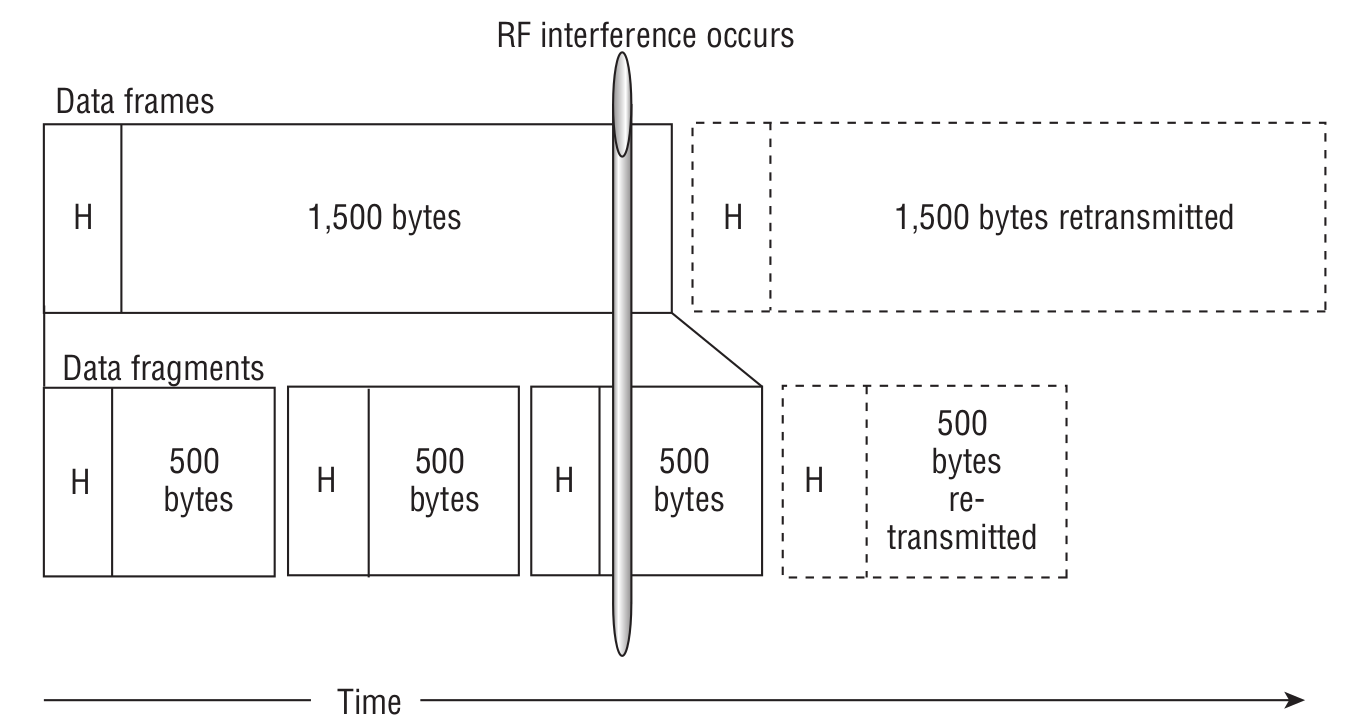
On the one hand, it does increase overhead. On the other, if a collision occurs, you only have to resend a small chunk instead of an entire jumbo frame, which actually improves throughput.
The smoking gun will be the presence of A‑MSDU (Aggregated MAC Service Data Unit) and A‑MPDU (Aggregated MAC Protocol Data Unit). To make things a bit clearer, let’s define a few more terms first.
Put simply, MSDU is the payload that carries an IP packet plus some LLC (Logical Link Control) data. An MPDU is an 802.11 frame, and PLCP is the Physical Layer Convergence Procedure. Here’s what the A-MSDU aggregation process looks like.
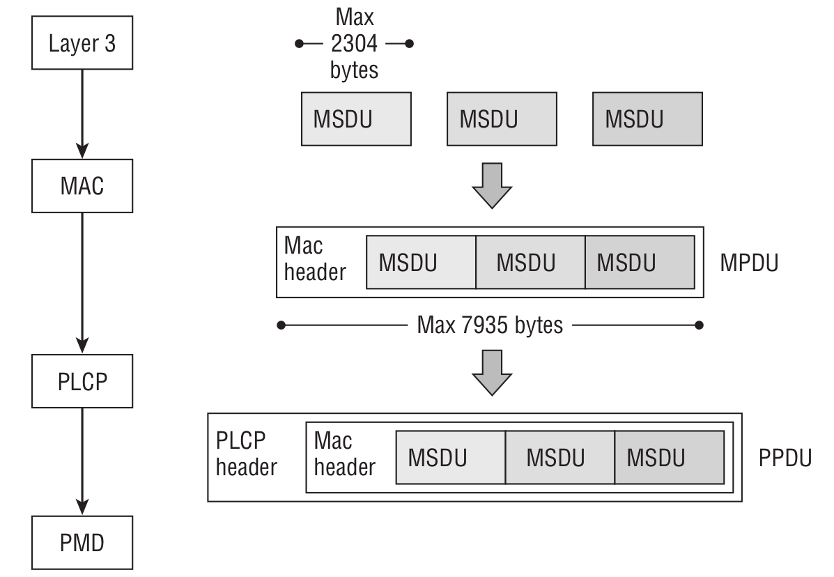
If encryption is enabled, multiple MSDUs are encrypted as a single unit. Keep in mind that MSDUs can be aggregated into one MPDU when the DA and SA addresses map to the same RA and TA.
Here’s what the A-MPDU aggregation process looks like.
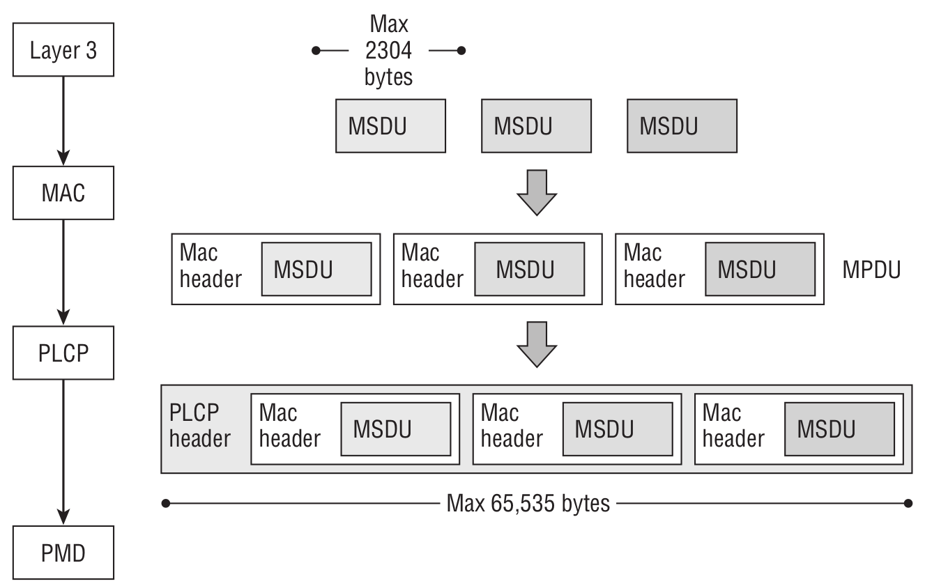
When encryption is enabled, there’s an important difference: each MPDU is encrypted separately. Also keep in mind that all MPDUs within an A‑MPDU must have the same destination address.
For those who want to dig deeper into 802.11, I can recommend a couple of resources (in addition to the IEEE 802.11 standard itself). Start with My CWAP Study Notes, and as a complement, check out this resource. And don’t forget the books:
- CWAP Certified Wireless Analysis Professional Official Study Guide Exam PW0-270;
- CWAN Certified Wireless Network Administrator Official Study Guide Exam PW0-105.
Enough theory—let’s get practical!
I hope you made it through the finer points of 802.11 with your sanity intact and are ready to build a hardware sniffer. Let’s dive in! As always, we’ll start by defining the problem.
Our goals
First and foremost, we want a straightforward connection to a PC/laptop—i.e., USB. Not every laptop has Ethernet/LAN, and not every Wi‑Fi adapter can be switched into promiscuous/monitor mode. There’s a list of adapters that support this mode here: https://www.wirelesshack.org/best-kali-linux-compatible-usb-adapter-dongles.html
Second, the ability to switch channels on the fly while capturing. We want flexible filtering of incoming packets—e.g., capture only Control frames or only Data frames, and optionally filter by specific MAC or IP addresses.
Implement initial packet analysis on the device: if a complete packet arrives, forward it to the host; if it’s a fragmented or aggregated frame, wait for the remaining parts, reassemble it, and only then send it to the host.
Naturally, Wireshark should be able to display the captured traffic in real time.
Another obvious ask: if you know the password to the Wi‑Fi network you’re monitoring, it would be great to have a magic function like decrypt_message(*ptr_message, *WPA_WPA2_key) that outputs the decrypted payload for further analysis.
Unlike the ESP8266, the ESP32 has a configurable hardware buffer for receiving and transmitting 802.11 frames. We can adjust the number of buffers, with each buffer being 1600 bytes, which is already enough to capture a frame. From my experiments, 1600 bytes is sufficient for Wi‑Fi sniffing. However, note an important caveat — the ESP32 (more precisely, the driver provided in the SDK) supports the following frame types in promiscuous mode:
- 802.11 Management frame;
- 802.11 Data frame, including MPDU, AMPDU, AMSDU, etc;
- 802.11 MIMO frame, for MIMO frame, the sniffer only dumps the length of the frame.
And it does not support:
- 802.11 Control frame;
- 802.11 error frame, such as the frame with a CRC error, etc.
If you read the intro on how Wi‑Fi works, you’ll realize it’s not a big deal that the ESP32 doesn’t support full-stack 802.11 frames: besides being able to listen to incoming frames, you can also transmit some. For that, there’s the esp_wifi_80211_tx function. There are caveats, though — for now you can only send beacon, probe request/probe response, action, and non‑QoS data frames.
Now, a bit of code that captures Wi‑Fi traffic.
wifi_init_config_t cfg = WIFI_INIT_CONFIG_DEFAULT();
wifi_country_t wifi_country = {
  .cc="CN",
  .schan=1,
  .nchan=13,
  .policy=WIFI_COUNTRY_POLICY_AUTO
};
nvs_flash_init();
tcpip_adapter_init();
ESP_ERROR_CHECK(esp_event_loop_init(event_handler, NULL));
ESP_ERROR_CHECK(esp_wifi_init(&cfg));
ESP_ERROR_CHECK(esp_wifi_set_country(&wifi_country));
ESP_ERROR_CHECK(esp_wifi_set_storage(WIFI_STORAGE_RAM));
ESP_ERROR_CHECK(esp_wifi_set_mode(WIFI_MODE_NULL));
ESP_ERROR_CHECK(esp_wifi_start());
ESP_ERROR_CHECK(esp_wifi_set_channel(WIFI_CHANNEL, WIFI_SECOND_CHAN_NONE));
ESP_ERROR_CHECK(esp_wifi_set_promiscuous_rx_cb(&sniffer_wifi));
Since we’re working with the ESP32 through the SDK, we start by initializing Wi‑Fi properly. In the last line, we register the callback that will be invoked whenever a new frame is captured.
Since I’m using the ESP32-PICO-KIT V4, the dev board can be connected to USB out of the box via a CP2102-based UART-to-USB bridge. Accordingly, UART initialization is required.
uart_config_t uart_cfg = {
  .baud_rate = UART_2_PC_BAUD_RATE,
  .data_bits = UART_DATA_8_BITS,
  .parity    = UART_PARITY_DISABLE,
  .stop_bits = UART_STOP_BITS_1,
  .flow_ctrl = UART_HW_FLOWCTRL_DISABLE
};
ESP_ERROR_CHECK(uart_param_config(UART_2_PC, &uart_cfg));
ESP_ERROR_CHECK(uart_set_pin(UART_2_PC,
  UART_PIN_NO_CHANGE,
  UART_PIN_NO_CHANGE,
  UART_PIN_NO_CHANGE, UART_PIN_NO_CHANGE));
ESP_ERROR_CHECK(uart_driver_install(UART_NUM_0, 4096, 0, 0, NULL, 0));
You can specify the packet types to capture using a filter:
wifi_promiscuous_filter_t filter = {
  .filter_mask = WIFI_PROMIS_FILTER_MASK_DATA
};
ESP_ERROR_CHECK(esp_wifi_set_promiscuous_filter(&filter));
Full list of packages that can be filtered:
// filter all packets
#define WIFI_PROMIS_FILTER_MASK_ALL           (0xFFFFFFFF)
// filter the packets with type of WIFI_PKT_MGMT
#define WIFI_PROMIS_FILTER_MASK_MGMT          (1)
// filter the packets with type of WIFI_PKT_CTRL
#define WIFI_PROMIS_FILTER_MASK_CTRL          (1<<1)
// filter the packets with type of WIFI_PKT_DATA
#define WIFI_PROMIS_FILTER_MASK_DATA          (1<<2)
// filter the packets with type of WIFI_PKT_MISC
#define WIFI_PROMIS_FILTER_MASK_MISC          (1<<3)
// filter the MPDU which is a kind of WIFI_PKT_DATA
#define WIFI_PROMIS_FILTER_MASK_DATA_MPDU     (1<<4)
// filter the AMPDU which is a kind of WIFI_PKT_DATA
#define WIFI_PROMIS_FILTER_MASK_DATA_AMPDU    (1<<5)
// filter all control packets
#define WIFI_PROMIS_CTRL_FILTER_MASK_ALL      (0xFF800000)
// filter the control packets with subtype of Control Wrapper
#define WIFI_PROMIS_CTRL_FILTER_MASK_WRAPPER  (1<<23)
// filter the control packets with subtype of Block Ack Request
#define WIFI_PROMIS_CTRL_FILTER_MASK_BAR      (1<<24)
// filter the control packets with subtype of Block Ack
#define WIFI_PROMIS_CTRL_FILTER_MASK_BA       (1<<25)
// filter the control packets with subtype of PS-Poll
#define WIFI_PROMIS_CTRL_FILTER_MASK_PSPOLL   (1<<26)
// filter the control packets with subtype of RTS
#define WIFI_PROMIS_CTRL_FILTER_MASK_RTS      (1<<27)
// filter the control packets with subtype of CTS
#define WIFI_PROMIS_CTRL_FILTER_MASK_CTS      (1<<28)
// filter the control packets with subtype of ACK
#define WIFI_PROMIS_CTRL_FILTER_MASK_ACK      (1<<29)
// filter the control packets with subtype of CF-END
#define WIFI_PROMIS_CTRL_FILTER_MASK_CFEND    (1<<30)
// filter the control packets with subtype of CF-END+CF-ACK
#define WIFI_PROMIS_CTRL_FILTER_MASK_CFENDACK (1<<31)
It’s located in the esp_wifi_types. file.
Correspondence
I sent a long email to Espressif support asking them to expand the SDK’s Wi‑Fi capabilities so we can receive and transmit raw 802.11 frames without restrictions. They said they’d think it over and add it to the roadmap. So, dear reader, if you also want the ESP32 to fully support sending and receiving all 802.11 frames, include at least USB 2.0, add 5 GHz support, and provide a magic_function that can decrypt captured data when you have the Wi‑Fi password, drop by the forum thread What would you like to see in The Next Chip? and share your requests. You might have more great ideas for the next-gen ESP32—don’t hesitate to write them up.
In this file, besides the filter defines, there’s also a useful struct:
wifi_pkt_rx_ctrl_t:
typedef struct {
  // Received Signal Strength Indicator(RSSI) of packet. unit: dBm
  signed rssi:8;
  // PHY rate encoding of the packet. Only valid for non HT(11bg) packet
  unsigned rate:5;
  unsigned :1; // reserve
  unsigned sig_mode:2; // 0: non HT(11bg) packet; 1: HT(11n) packet; 3: VHT(11ac) packet
  unsigned :16; // reserve
  // Modulation Coding Scheme. If is HT(11n) packet, shows the modulation, range from 0 to 76(MSC0 ~ MCS76)
  unsigned mcs:7;
  // Channel Bandwidth of the packet. 0: 20MHz; 1: 40MHz
  unsigned cwb:1;
  unsigned :16; // reserve
  unsigned smoothing:1; // reserve
  unsigned not_sounding:1; // reserve
  unsigned :1; // reserve
  // Aggregation. 0: MPDU packet; 1: AMPDU packet
  unsigned aggregation:1;
  // Space Time Block Code(STBC). 0: non STBC packet; 1: STBC packet
  unsigned stbc:2;
  // Flag is set for 11n packets which are LDPC
  unsigned fec_coding:1;
  // Short Guide Interval(SGI). 0: Long GI; 1: Short GI
  unsigned sgi:1;
  // noise floor of Radio Frequency Module(RF). unit: 0.25dBm
  signed noise_floor:8;
  // ampdu cnt
  unsigned ampdu_cnt:8;
  // primary channel on which this packet is received
  unsigned channel:4;
  // secondary channel on which this packet is received. 0: none; 1: above; 2: below
  unsigned secondary_channel:4
  unsigned :8; // reserve
  // timestamp. The local time when this packet is received. It is precise only if modem sleep or light sleep is not enabled. unit: microsecond
  unsigned timestamp:32;
  unsigned :32; // reserve
  unsigned :31; // reserve
  // antenna number from which this packet is received. 0: WiFi antenna 0; 1: WiFi antenna 1
  unsigned ant:1;
  // length of packet including Frame Check Sequence(FCS)
  unsigned sig_len:12;
  unsigned :12; // reserve
  // state of the packet. 0: no error; others: error numbers which are not public
  unsigned rx_state:8;
} wifi_pkt_rx_ctrl_t;
This structure is available every time the callback is triggered to signal that a new frame is ready. As you can see, it includes plenty of useful information you can leverage when processing packets.
A meticulous reader might say, “Hold on — we’re sniffing Wi‑Fi, where 802.11n can hit 600 Mbps, but our connection to the computer is a humble UART running at the standard 115,200, which is clearly slower than Wi‑Fi. Something’s fishy here!” You’d be right to a point, but let me add a few caveats and share some observations.
- 1) First, in practice the dev board ran just fine at 921,600 baud.
- 2) Second, if you swap the UART–USB bridge for a newer CP2102N, you can push the rate up to 3 Mbaud (https://www.silabs.com/documents/public/data-sheets/cp2102n-datasheet.pdf).
- 3) Third, Espressif officially confirmed that the ESP32’s UART can operate at 5 Mbps.
- 4) Fourth, we can configure the filter so it doesn’t capture every packet.
In the end, our experiments did yield a sustained data flow—at least for a while. But there’s a downside: the development board runs hot. You won’t be frying eggs on it, but it’s definitely not cool either. Then again, the board only costs about ten dollars.
Trial by Fire
I set up an access point with a simple web server on one of the ESP32s. Initially, I disabled encryption. I connect to the AP from a laptop and start pinging. On the second ESP32, I run a sniffer.
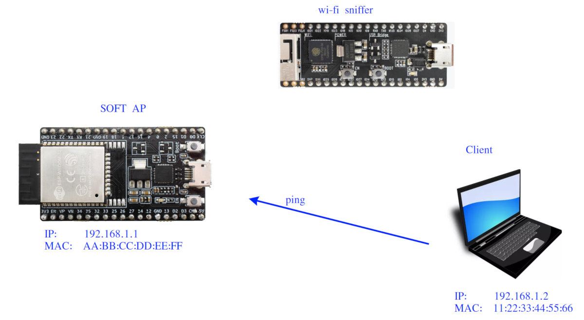
The sniffer captured the following packet.

Now let’s break down some bytes:
MAC HEADER → FC: 88 02
MAC HEADER → Duration/ID 30 00
MAC HEADER → Address1 11 22 33 44 55 66
MAC HEADER → Address2 AA BB CC DD EE FF
MAC HEADER → Address3 AA BB CC DD EE FF
MAC HEADER → SEQUENCE CTRL 90 2F
MAC HEADER → QOS 00 00
Next up, the LLC & SNAP header comes into play: AA . Starting at 08 00 in the LLC & SNAP header, you can probably already recognize what’s coming—0x0800 is the EtherType for IPv4, which is where ping (ICMP echo) lives. The last four bytes are the checksum (frame check sequence).
Acknowledgments
Thanks to a colleague who, after hearing about my project, helped me get a CC3220SF-based dev board — CC3220SF-LAUNCHXL. On the one hand, this microcontroller isn’t exactly a performance monster — a modest 80 MHz Cortex‑M4 (vs. a 240 MHz Xtensa LX6), and TI’s RAM is just 256 KB compared to the ESP32’s 520 KB. However, there’s an interesting twist — according to this wiki, we can put it into a promiscuous mode that lets us both receive all 802.11 frames and transmit arbitrary raw packets.
Beyond its flexible 802.11 transmit/receive capabilities, the board, in my opinion, offers a fairly flexible system for filtering incoming packets:
In other words, you can set up something along these lines here (see section 10.3.2 of the “CC3120, CC3220 SimpleLink Wi‑Fi and Internet of Things Network Processor Programmer’s Guide”):
- Receive WLAN data broadcast frames only from two specific MAC addresses.
- Do not receive WLAN unicast frames from a certain SRC_IP address range.
- If a unicast frame is received from MAC address
AA., increase counter_1.BB. CC. DD. EE. FF - If a unicast frame is received from MAC address
CC., increase counter_2.HH. II. JJ. KK. LL - If a unicast UDP frame is received from MAC address
AA.orBB. CC. DD. EE. FF CC., pass only packets from port 5001.HH. II. JJ. KK. LL
In conclusion
Of course, this project isn’t a revolution—and in places I probably reinvented the wheel—because ESP32-based sniffers already exist, for example ArduinoPcap, ESP32-WiFi-Sniffer, or Espressif’s own sample. But I’m happy with it. 🙂 “Let a hundred flowers bloom; let a hundred schools contend,” especially since every implementation has its quirks, and when it’s your own device you can tailor it exactly to your preferences and use cases.