
In the previous article, I mentioned that ADS-B is a part of the larger Mode S protocol used to identify and track aircraft. ADS-B makes it possible to track an airplane equipped with a special transponder. This transponder sends data about the aerial vessel (altitude, coordinates, speed, etc.) on a regular basis. Anyone can receive this information since the protocol has no protection or encryption.
This article explains how to generate and transmit your own ADS-B signals. To avoid disturbing anyone, you will use your own receiver to pick up this signal. Note that this isn’t a guide for technicians who equip planes with transponders. This is just an example demonstrating that everyone can analyze and spoof an unprotected signal.
warning
Under no circumstances should you repeat this outside of your lab! Operating on the airwaves without permission can be prosecuted by law. Neither the author nor the Editorial Board can be held liable for any damages caused by improper usage of this publication.
Test Environment
A test environment is required to see what you are doing without interfering with airport equipment. Airport authorities probably won’t appreciate your experiments! Furthermore, they could estimate damages and charge you. To avoid this, I used two SDR devices at a minimum power level in a shielded room. In addition, I used signals at a frequency of some 1 GHz that barely propagate beyond the horizon.
I used two decent and quite popular SDRs: HackRF as a transmitter and BladeRF as a receiver. The software component of the reception is based on the dump1090 program familiar to you from the previous article. It parses Mode S (as you know, ADS-B is a part of it) signals in real-time and displays them in a readable format.
The test environment should look approximately like this.

To ensure stable operation, you have to attach whip antennas to both SDR devices: otherwise, they won’t work properly.
Configuring BladeRF
The step-by-step BladeRF setup for reception has been described in the previous article. If you followed my instructions, you should already have the dump1090 utility and the required firmware installed on your SDR. If this is the case, you can skip the section below.
Out-of-the-box, the factory BladeRF firmware doesn’t support dump1090; to ensure compatibility, you have to manually configure them. The first step is to download firmware compatible with ADS-B from the developer’s official website:
wget https://www.nuand.com/fpga/adsbxA4.rbf
After that, flash the downloaded file to the BladeRF:
bladerf-cli -i adsbxA4.rbf
Next, you have to install two programs: bladeRF-adsb and dump1090. The first one is required to stream data directly from SDR to dump1090.
Download and compile dump1090:
git clone https://github.com/mutability/dump1090.git
cd dump1090
make
./dump1090 --net-only --raw --interactive
Start dump1090 and compile the bridge:
git clone https://github.com/Nuand/bladeRF-adsb
cd bladeRF-adsb/bladeRF_adsb
wget http://nuand.com/fpga/adsbx40.rbf
wget http://nuand.com/fpga/adsbx115.rbf
make
./bladeRF_adsb
Voila! Everything required to receive and decode ADS-B signals has been set up. Now you can pick up signals from airplanes (yes, even in your room), especially if an airplane is flying nearby or you have a good antenna.
ViralAir
To generate ADS-B messages, I wrote a utility called ViralAir and uploaded it to GitHub. To continue the experiment, download and compile it:
git clone https://github.com/st3rv04ka/ViralAir
cd ViralAir
go build cmd/viralair/main.go
After compilation, a file called main will appear; it generates ready-to-transmit files. The format of this file is fully compatible with HackRF (it might also be compatible with other SDRs – but I didn’t check this). To verify that everything works properly, let’s create a test aircraft with the callsign 0xDEADBE flying at an altitude of 9999 feet:
./main -altitude 9999.0 --icao 0xDEADBE
A file called Samples. should appear in the current directory. If it’s there, then everything is working correctly and you can proceed.
ADS-B Structure
Preparations
As you remember from the previous article, an ADS-B message can be either 56 or 112 bits long. Its length determines the type of transmitted information, which is saved to the TC (Type Code) field of the message. A typical 112-bit message looks as shown below.

As you might have noticed, there is no TC field there since it’s hidden within the ME field. The thing is, ADS-B is just a part of the larger Mode S protocol, and the above scheme shows the structure of a Mode S message. All fields specific to ADS-B are contained within the data field (ME) of the Mode S message.
Let’s refresh the purpose of other fields in the packet:
- DF (downlink format) determines the signal type in Mode S. For ADS-B, it’s always 17;
- CA (transponder capability) specifies the transponder type. In theory, you can set any value in it, but for practical purposes, let’s use 6 (a level 2+ transponder);
-
ICAO is the unique aircraft identifier. These 24 bits can contain anything; in this experiment, I am going to use an aircraft whose callsign is
0xDEADBE; and - ME is the ADS-B message itself. It can contain altitude, speed, or coordinates. For simplicity, I will only transmit coordinates (TC = 11) without speed or altitude. These two parameters aren’t inferior to coordinates, but I want to focus primarily on CPR encoding.
CPR
You might remember from the previous article how I struggled with CPR and simplified grids used to transmit data in small messages. Because of these grids, ADS-B has two types of coordinate messages: even and odd ones. To determine the exact location of an aircraft, you need both of them. Creating such packets is even more challenging than receiving them.
Let’s go through my Go code that converts coordinates into CPR data:
func nl(declatIn float64) float64 { // Near the poles, there are few sectors, so just one is returned. if math.Abs(declatIn) >= 87.0 { return 1.0 } return math.Floor( (2.0 * math.Pi) * math.Pow( math.Acos(1.0 - (1.0-math.Cos(math.Pi/(2.0*latz))) / math.Pow(math.Cos((math.Pi/180.0) * math.Abs(declatIn)), 2)), -1))}func dlon(declatIn float64, ctype int, surface int) float64 { var tmp float64 if surface == 1 { tmp = 90.0 } else { tmp = 360.0 } nlcalc := math.Max(nl(declatIn)-float64(ctype), 1) return tmp / nlcalc}// Encoding to CPRfunc CprEncode(lat float64, lon float64, ctype int, surface int) (int, int) { var scalar float64 if surface == 1 { scalar = math.Pow(2, 19) } else { scalar = math.Pow(2, 17) } dlati := dlat(ctype, surface) yz := math.Floor(scalar*((math.Mod(lat, dlati))/dlati) + 0.5) dloni := dlon(lat, ctype, surface) xz := math.Floor(scalar*((math.Mod(lon, dloni))/dloni) + 0.5) return int(yz) & ((1 << 17) - 1), int(xz) & ((1 << 17) - 1)}Yes, the above code looks quite sophisticated, but its underlying algorithms are actually fairly simple once you get past the complicated math.
Let’s go through it step by step, starting with the nl( function. This function calculates the number of sectors at a given latitude. The logic is straightforward: the closer to the poles, the fewer sectors of a given size can fit on a single line of latitude. Actual sectors in CPR look as follows:

To avoid delving into complex math, the returned sector count for latitudes greater than 87 degrees will be 1. The formula was taken from the official protocol documentation, which presents it in a rather daunting form.

After nl(, comes the dlon(function. You already have the number of sectors for a given latitude, and now you have to calculate an interval to evenly distribute these sectors around the circle and ensure they are all equal to each other. It’s important to take into account whether the aircraft is on the ground or in the air. If the aircraft is in the air, you divide 360 by the number of intervals minus the message type (even or odd). The result is returned at the end of the function. The function dlat( does more or less the same thing for longitude, so I won’t describe it separately.
Now let’s move on to the main CPR calculation function. After obtaining the number of sectors, you can directly calculate aircraft coordinates. For this purpose, you need a multiplier that can be found in the protocol documentation (it’s hidden deep within the formulas). The multiplier is 217 for the air and 219 for the ground.


After the encoding, the resulting value must be compressed to 17 bits; this operation is performed when the function returns results.
PI
If you think the hard part is over, think again! The second problem that has to be solved to transmit your signals is computing the checksum (CRC) or parity bits. You have to compute 24 bits and add them at the end of the message for integrity checking. Tools like dump1090 rely on these bits. The problem is that the formula looks as follows.

In pseudocode, this function looks approximately like this:
generator = 1111111111111010000001001
# 11 + 3 zero bytes
data_hex = 8D406B902015A678D4D220[000000]
# 88 bits
data = 1000110101000000011010 1110010000001000000001
       0101101001100111100011 0101001101001000100000
      [000000000000000000000000]  # 24 bits
FOR i FROM 0 TO (112-24):
  IF data[i] IS 1:
    data[i:i+24] = data[i:i+24] XOR generator
remainder = data[-24:]
# Result: 101010100100101111011010, or AA4BDA in HEX
The generator is a constant identified specifically for this algorithm as the most effective one. In the loop, you simply iterate through all bits from 0 to 88 (112 minus 24 because the last 24 bits are what you are filling right now) and apply an XOR with the generator. The resulting 24 bits must be added to your message to complete the data packet. Here’s how I implemented it in ViralAir:
const ( GENERATOR = "1111111111111010000001001" )func Crc(msg string, encode bool) string { msgbin := []rune(misc.Hex2bin(msg)) generator := []int{} for _, char := range GENERATOR { generator = append(generator, int(char-'0')) } if encode { for i := len(msgbin) - 24; i < len(msgbin); i++ { msgbin[i] = '0' } } for i := 0; i < len(msgbin)-24; i++ { if msgbin[i] == '1' { for j := range generator { msgbin[i+j] = rune('0' + (int(msgbin[i+j]-'0') ^ generator[j])) } } } reminder := string(msgbin[len(msgbin)-24:]) return reminder}The Go implementation is similar to the pseudocode, so I won’t analyze it in detail.
Putting it all together
Now that you have all the utility functions, you can start creating the packet! First, you encode the altitude using the encodeAltModes(function.
// Encode altitudefunc encodeAltModes(alt float64, surface int) int { mbit := 0 qbit := 1 encalt := int((int(alt) + 1000) / 25) var tmp1, tmp2 int if surface == 1 { tmp1 = (encalt & 0xfe0) << 2 tmp2 = (encalt & 0x010) << 1 } else { tmp1 = (encalt & 0xff8) << 1 tmp2 = 0 } return (encalt & 0x0F) | tmp1 | tmp2 | (mbit << 6) | (qbit << 4)}Depending on the altitude, different divisors can be used. For regular aircraft, it’s 25, but other values (e.g. 100) can be used as well. Such divisors are required for aircraft flying higher than normal. The divisor value is determined by the qbit parameter. The purpose of the divisor is to specify the size of the interval used for altitude.
Specifying altitude in normal units rather than feet would be too simple: the protocol developers decided to divide the altitude into intervals N feet in size and specify the number of such an interval. Accordingly, N is your divisor (i.e. the number of feet per interval). For your imaginary aircraft, a divisor of 25 feet ensures an accuracy of some 7.6 meters.
With regards to qbit, the protocol documentation states as follows:
This field will contain barometric altitude encoded in 25 or 100-foot increments (as indicated by the Q Bit). All zeroes in this field will indicate that there is no altitude data.
So, if qbit is set to 0, the divisor becomes 100, which can be useful when the altitude is too high and it’s difficult to fit its value into a message. In ViralAir, only a divisor of 25 is supported, though 100 can be added fairly easily – you can try implementing it yourself as an exercise!
The result returned by the function for an altitude of 9999 feet is shown below:
2024/01/15 03:40:37 [+] Encode altitude [9999.000000] with the surface flag [0]2024/01/15 03:40:37 [+] Encoded altitude [0x377]
The next step is to create two messages (even and odd); let’s start with the even one. The first part of any ADS-B message is its type. For ADS-B, the DF (Message Type for Mode S) is always 17 (i.e. this is a constant in the code). The following fields are CA (transponder level) and ICAO (aircraft number). CA and ICAO can be set as arguments when you start ViralAir.
// Format + CA + ICAOdataEven = append(dataEven, byte((format<<3)|ca))dataEven = append(dataEven, byte((icao>>16)&0xff))dataEven = append(dataEven, byte((icao>>8)&0xff))dataEven = append(dataEven, byte((icao)&0xff))Now let’s add the longitude, latitude, and altitude to the frame:
// Evenlog.Printf("[+] Encode even frame with lat [%f] and lon [%f]", lat, lon)evenLat, evenLon := cpr.CprEncode(lat, lon, 0, surface)log.Printf("[+] Encoded even frame lat [0x%02x] and lon [0x%02x]", evenLat, evenLon)// Oddlog.Printf("[+] Encode odd frame with lat [%f] and lon [%f]", lat, lon)oddLat, oddLon := cpr.CprEncode(lat, lon, 1, surface)log.Printf("[+] Encoded odd frame lat [0x%02x] and lon [0x%02x]", oddLat, oddLon)When you run the program, the encoded values are displayed in the console:
./main -altitude 9999.0 -icao 0xDEADBE -latitude 11.33 -longitude 11.22<...>2024/01/15 03:40:37 [+] Encode even frame with lat [11.330000] and lon [11.220000]2024/01/15 03:40:37 [+] Encoded even frame lat [0x1c6d4] and lon [0x19d86]2024/01/15 03:40:37 [+] Encode odd frame with lat [11.330000] and lon [11.220000]2024/01/15 03:40:37 [+] Encoded odd frame lat [0x1b6b6] and lon [0x18d91]<…>
Bytes for both packets are ready; time to add them to the frame:
// Lat + Lot + Alt (even)dataEven = append(dataEven, byte((tc<<3)|(ss<<1)|nicsb))dataEven = append(dataEven, byte((encAlt>>4)&0xff))dataEven = append(dataEven, byte((encAlt&0xf)<<4|(time<<3)|(ff<<2)|(evenLat>>15)))dataEven = append(dataEven, byte((evenLat>>7)&0xff))dataEven = append(dataEven, byte(((evenLat&0x7f)<<1)|(evenLon>>16)))dataEven = append(dataEven, byte((evenLon>>8)&0xff))dataEven = append(dataEven, byte((evenLon)&0xff))The frame data are ready; all you have to do at this point is append the checksum.
// Convert to hexvar sbEven strings.Builderfor _, b := range dataEven[:11] { sbEven.WriteString(fmt.Sprintf("%02x", b))}dataEvenString := sbEven.String()log.Printf("[+] Even frame without CRC [%s]", dataEvenString)// Calculate CRCdataEvenCRC := misc.Bin2int(crc.Crc(dataEvenString+"000000", true))log.Printf("[+] Even data CRC [%02x]", dataEvenCRC)// Append CRCdataEven = append(dataEven, byte((dataEvenCRC>>16)&0xff))dataEven = append(dataEven, byte((dataEvenCRC>>8)&0xff))dataEven = append(dataEven, byte((dataEvenCRC)&0xff))log.Printf("[+] Even data [%02x]", dataEven)After that, the complete Mode S frame will appear in the terminal. You can use it in any way: transmit it, decode it online, or even print it out and hang on your bedroom wall.
2024/01/15 03:40:37 [+] Even data [8ddeadbe5837738da99d861b04b3]2024/01/15 03:40:37 [+] Odd data [8ddeadbe5837776d6d8d9121b103]
Now you are just one little step away from sending the signal: it has to be modulated.
Transmission
Modulation
To transmit your bytes over the air, you have to convert them into a format understandable to HackRF. This format is pretty simple: all bytes must be encoded as complex numbers and saved to a file.
ADS-B uses Manchester encoding, which means that a one is encoded as 01; while a zero, as 10. For better understanding, see the image below.

In other words, you have to encode the binary representation of each byte according to the above-described scheme, and that’s it. All these are basic operations with numbers that can be easily performed using any programming language. Below is my implementation in Go:
func Frame1090esPpmModulate(even, odd []byte) []byte { var ppm []byte for i := 0; i < 48; i++ { ppm = append(ppm, 0) } ppm = append(ppm, 0xA1, 0x40) for _, byteVal := range even { word16 := misc.Packbits(manchesterEncode(^byteVal)) ppm = append(ppm, word16[0]) ppm = append(ppm, word16[1]) } for i := 0; i < 100; i++ { ppm = append(ppm, 0) } ppm = append(ppm, 0xA1, 0x40) for _, byteVal := range odd { word16 := misc.Packbits(manchesterEncode(^byteVal)) ppm = append(ppm, word16[0]) ppm = append(ppm, word16[1]) } for i := 0; i < 48; i++ { ppm = append(ppm, 0) } return ppm}Don’t forget to include the preamble: a special bit sequence at the beginning of the frame that helps the receiver identify the beginning of the message. In this particular case, this is 0xA1 0x40, which corresponds to the Mode S preamble.
The resulting bits should be modulated into PPM (pulse-position modulation). How PPM works and how it differs from other modulation methods can be seen in the image below.

Note that you are going to encode a digital signal, not an analog one (i.e. the signal has to be represented as complex numbers). I won’t delve into the nuances since, for the purposes of this experiment, you only need two such numbers without any calculations. A complex number consists of two components (I and Q): for a high bit level, they should be set to the maximum value; while for a low bit level, to the minimum value.
func GenerateSDROutput(ppm []byte) []byte { bits := misc.Unpackbits(ppm) var signal []byte for _, bit := range bits { var I, Q byte if bit == 1 { I = byte(127) Q = byte(127) } else { I = 0 Q = 0 } signal = append(signal, I, Q) } return signal}Voila! Now write the result to a file and you’ll get your much-desired Samples..
On the air!
Finally, you can breathe a sigh of relief. After setting up a test system, generating a signal file, and configuring all the equipment, you can now transmit data about your fictitious aircraft back to yourself. Congrats!
Turn on the receiver as described above and transmit the signal using HackRF:
~/P/ViralAir (main)> hackrf_transfer -t Samples.iq8s -f 1090000000 -s 2000000 -x 47 -Rcall hackrf_set_sample_rate(2000000 Hz/2.000 MHz)call hackrf_set_hw_sync_mode(0)call hackrf_set_freq(1090000000 Hz/1090.000 MHz)Stop with Ctrl-C 3.9 MiB / 1.000 sec = 3.9 MiB/second, average power -6.5 dBfs 3.9 MiB / 1.000 sec = 3.9 MiB/second, average power -6.5 dBfs 3.9 MiB / 1.000 sec = 3.9 MiB/second, average power -6.5 dBfs 4.2 MiB / 1.000 sec = 4.2 MiB/second, average power -6.5 dBfs
The -t argument is the signal file you’ve generated; -f sets the transmission frequency (for ADS-B, it’s 1090 MHz or 1,090,000,000 Hz); while -s specifies the sampling rate. The last two arguments control the transmission power and looping. Why loop? Since you only have two messages, they will disappear from the dump1090 window immediately after the transmission.
Now let’s take a look at the receiver!

Your aircraft DEADBE is visible in the table! It’s flying at an altitude of 9975 feet (due to encoding inaccuracies), and it even can be seen on the map.
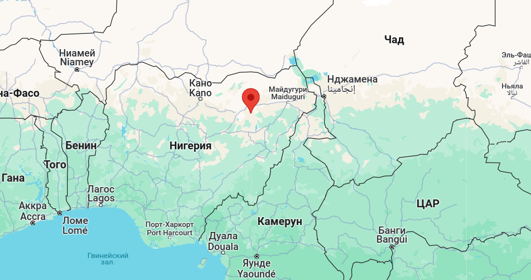
Right now, it’s flying somewhere in the Nigerian skies.
Happy hacking!